List of symbols
52 ASVxxx
11
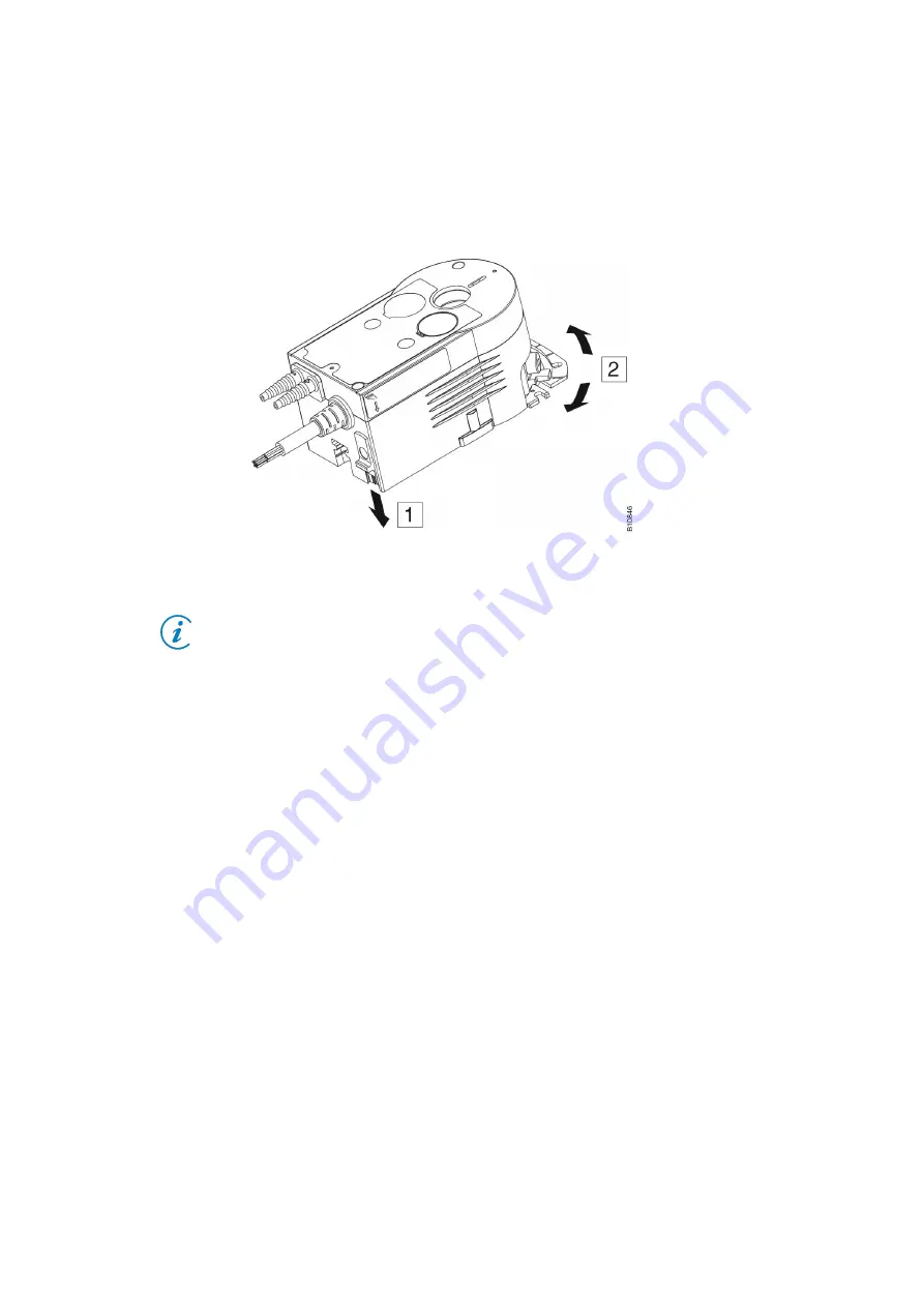
The next step is to check that the damper moves easily. Release the
damper lock on the ASV and move the damper in both directions as far as
it will go. You should be able to move the damper without much effort. If
not, try to unjam the damper by moving it back and forth. If the damper will
not move, repair it.
Fig. 3: Releasing the lock
Note: Most VAV boxes (e.g. Trox) do not need any maintenance.
Note down any improper modifications and eliminate them.
3.3
Testing the damper using the CASE VAV parameterising software
Connect the ASV unit to the PC with the USB-RS-485 adapter and start up
the latest CASE VAV software. Use the SLC protocol to connect to the
VAV compact controller. The current SLC address of the device can be
found in the commissioning protocol. First adjust the angle of rotation on
the ASV and note down the working range. Then use the “Manual
operation” function and set the damper to “Open” and “Closed”. You can
see the position of the damper blade from outside using a marking on the
damper spindle. If not, you can derive the position of the damper blade
using the actual values of the volume flow. The maximum volume flow
must be reached when the damper is open. If the function is not
c
ompletely working, you can use the “Angle of rotation” and “Adjust angle
of rotation” functions to move to the two limit switches of the actuator and
calculate the angle of rotation again. Test the damper again.
If the end positions (open, closed) are still not reached, release the lock of
the ASV 115 and check the alignment of the damper adapter to the
damper blade (see Fig. 2).
Note down the results.
3.4
Measurement of the duct pressure
In manual mode, completely close the damper of the VAV box and use the
T-hoses to connect the pressure gauge on the (+) hose to the differential
pressure outlet of the VAV box. Measure in relation to atmospheric


