


51.362/4
AVM 105S...115S
Sauter Components
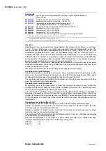
Coding switch for selecting the characteristic
On
Off
Signal
Signal
v
Signal
v
Signal
Signal
v
Signal
Signal
v
Signal
v
= %
x
2
lin
= %
lin
v
v
v
v
v
Signal
Signal
On
Off
On
Off
On
Off
On
Off
B10705
1 2 3
1 2 3
1 2 3
1 2 3
1 2 3
Stroke
Stroke
Stroke
Stroke
Stroke
Desired
character.
curve
Switch coding
Characteristic
curve for valve
Characteristic
curve for drive
Effective on valve
Stroke
Stroke
Stroke
Stroke
Eq
u
a
l
pe
rc
e
nt
a
ge
Q
uad
rat
ic
Li
near
E
qua
l
pe
rc
en
tag
e
Li
near
= factory setting
Stroke
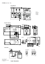
AVM 115S
Split-range unit, accessory 0361529 001
The starting point U
0
and the control span
U can be set using the potentiometer. This makes it
possible to activate several regulating units in sequence or in cascade using the controller’s control
signal. The input signal (partial range) is amplified into an output signal of 0...10 V. This accessory
cannot be fitted in the actuator, but should be located externally in an electric distribution box.
CASE Drives
PC tool, accessory 0372462 001
CASE Drives
enables all the actuator's parameters to be set and viewed on site. Connection is via a
serial port on the PC (laptop) and a socket on the actuator. The set comprises: software including
installation and operating instruction, fitting instructions, connectors, cable (1.2 metres in length) and
an interface converter for the PC. The application is designed for commissioning/ service technicians
and for experienced users.
The last setting (i.e. whether with coding switch or
CASE Drives
) has priority. This setting is active
when the valve's running time or characteristic is changed via the coding switch. To ensure that the
settings with
CASE Drives
cannot be overwritten, the coding switch should be removed before setting
values through
CASE Drives
(special tool included).
7151362003 05


