


AVM 105S...115S
51.362/3
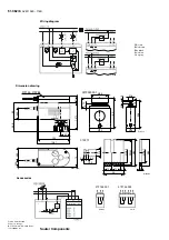
Components
After power has been applied, the stepping motor moves to the lower stop, connects to the valve
spindle and moves to the upper stop in the valve, thereby determining the closed position. Depending
on the control voltage, any stroke between 0 and 8 mm can then be obtained. Thanks to the
electronics unit, no steps can be lost, and the drive needs no periodical re-adjustment. Parallel
operation of more than one drive of the same type is guaranteed.
The feedback signal y
0
= 0...10 V corresponds to the effective stroke of 0 to 8 mm.
If the control signal (0...10 V) is interrupted and direction of operation 1 is connected, the valve closes
fully (0% position).
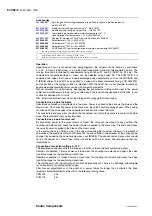
The valve’s characteristic can be selected using the coding switch. The characteristics can be
generated only if the drive is used as a continuous drive. Other switches enable the running times to
be set. These can be applied irrespective of which function (2-point, 3-point or continuous) has been
chosen.
Coding switch for setting the running time
AVM 105S
7,5 s
60 s ± 2
15 s
120 s ± 4
B10703
On
Off
On
Off
1 2 3
1 2 3
Run time
per mm
Switch coding
Run time for
8 mm stroke
= factory setting
AVM 115S
Coding switch for selecting the characteristic
Sauter
On
Off
v
v
v
= %
lin
lin
v
v
v
On
Off
On
Off
B10704
1 2 3
1 2 3
1 2 3
Signal
Signal
Signal
Signal
Signal
Signal
Stroke
Stroke
Stroke
Desired
character.
curve
Switch coding
Characteristic
curve for valve
Characteristic
curve for drive
Effective on valve
Stroke
Stroke
Eq
u
a
l
pe
rc
e
nt
a
ge
Li
ne
ar
Li
near
= factory setting
Stroke
AVM 105S
7151362003 05


