


26
REPLACEMENT OF PARTS
• Remove slotted metal clips from heat exchanger con-
nection pipes.
• Undo nut securing pipe from heat exchanger to 3-
way valve/bypass housing.
• Swing pipe away from 3-way valve/bypass housing
and pull down to disengage from heat exchanger pipe.
• Pull down pipe from pump to heat exchanger to dis-
engage from heat exchanger pipe.
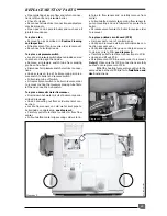
• Slide heat exchanger forwards and remove from
boiler,
see diagram 11.
• Fit replacement heat exchanger in reverse order to
removal.
• Reconnect electrical connector to high limit thermo-
stat.
• Open isolating valves on flow and return connections,
refill, vent and pressurise boiler.
• Check for leaks.
To replace combustion chamber insulation
• Remove combustion chamber cover as de-
scribed in ‘
Routine Cleaning and Inspection
’.
• Remove heat exchanger as described previously.
• Remove fan and flue hood as described in ‘
Rou-
tine Cleaning and Inspection
’.
Front panel:
• Lift front insulation panel free from retaining lugs
on combustion chamber cover.
Rear panel:
• Pull rear insulation panel free from retaining lug
at rear of combustion chamber by tilting forward.
• Fit replacement insulation panels in reverse or-
der to removal
• Refit combustion chamber cover.
Side panels:
• Pull out side panels.
To replace burner
• Remove burner as described in '
Routine Clean-
ing
and Inspection
'.
Assemble replacement burner, supplied in parts, as
follows:
• Fit burner injectors to burner injector bar and
tighten.
Note:
Make sure that injector size, marked on each
injector, is the same as that given in ‘
Technical Data
’
for the type of gas being used.
• Fit injector bar into burner, secure with retaining rods.
• Fit replacement burner into boiler in reverse or-
der to removal.
To replace burner injectors
• Remove burner as described in '
Routine Clean-
ing and Inspection
'.
• Pull out injector bar retaining rods and separate
injector bar from burner.
• Unscrew and remove injectors from injector bar.
• Fit replacement injectors to injector bar and
tighten.
Note:
Make sure that injector size, marked on each
injector, is the same as that given in ‘
Technical Data
’
for the type of gas being used.
• Reassemble burner and fit into boiler in reverse
order to removal.
To replace ignition electrode
• Remove burner as described in ‘
Routine Clean-
ing and Inspection
’.
• Undo and remove screw securing electrode onto
burner.
• Fit replacement electrode onto burner in reverse
order to removal.
• Refit burner into boiler in reverse order to removal.
To replace flame sense electrode
• Remove burner as described in ‘
Routine Clean-
ing and Inspection
’.
• Undo and remove screw securing electrode onto
burner.
• Fit replacement electrode onto burner in reverse
order to removal.
• Refit burner into boiler in reverse order to removal.
Diagram 11
Ech 040
To replace central heating expansion vessel
Replacement of the expansion vessel is not possi-
ble with the boiler on the wall.
Remove boiler from wall as described in '
To replace
storage vessel thermistor'.
• Undo pipe coupling on expansion vessel.
• Supporting expansion vessel, unscrew and re-
move screw securing expansion vessel to boiler.
• Lift vessel out of boiler.
• Fit replacement vessel to boiler in reverse order
to removal, ensuring that sealing washer is fitted to
pipe connection before tightening.
• Ensure that expansion vessel charge pressure is
0.5 bar (7.5 psi) using a pressure gauge. If neces-
sary, increase pressure using a car or cycle tyre
pump connected to the Schrader valve.
• Refit boiler onto fixing jig, tighten all connections
ensuring that all sealing washers are fitted before
tightening.
• Reconnect flue making sure that all joints are
properly connected.
• Open isolating valves on flow and return connec-
tions, refill, vent and pressurise boiler.
• Check for leaks.
• Reconnect all electrical connections and restore
electrical supply.
• Open gas cock, operate boiler and re-check all
joints for soundness.
To replace high limit thermostat
• Locate high limit thermostat on heating flow pipe
on left hand side of boiler.
• Disconnect electrical connection from thermostat
• Unclip thermostat from heating flow pipe.
• Fit replacement thermostat in reverse order to re-
moval.
• Refit connection to thermostat.


