


25
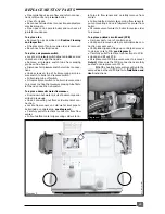
REPLACEMENT OF PARTS
Mec 140
• Remove screw securing cover onto gas valve
module,
see diagram 9.
• Remove cover and disconnect multi-plug from
module.
• Disconnect ignition and flame sense leads from
module.
• Withdraw module from gas valve.
• Fit replacement module, ensuring it is of the cor-
rect type for the boiler, in reverse order to removal.
• Reconnect ignition and flame sense leads, the
connections are uniquely sized to ensure correct
replacement.
• Reconnect multi-plug onto replacement module.
• Refit cover ensuring all sealing grommets are cor-
rectly located in module body.
To replace gas valve
• Ensure that gas supply to boiler is turned off at
gas cock.
• Remove gas valve module as described previ-
ously.
• Disconnect electrical connections to gas valve
modulating coil,
see diagram 9.
• Undo main gas supply nut from main burner.
Note:
The washer must be kept for use on
reassembly.
• Undo main gas union nut between gas valve sup-
ply pipe and gas inlet valve.
Note:
The washer must be kept for use on
reassembly.
• Disconnect plastic sensing pipe from gas valve
to base of sealed chamber.
• Unscrew and remove screws securing gas valve
bracket to boiler frame.
• Withdraw gas valve assembly.
• Using old gas valve as a guide, transfer gas pipes
from old gas valve to replacement gas valve.
• Fit replacement gas valve into boiler.
• Reconnect gas pipes in reverse order to removal.
• Refit electrical connections in reverse order to re-
moval, the polarity of the wires to the modulating
coil is not important.
To replace modulating coil
• Ensure that gas supply to boiler is turned off at
gas cock.
• Disconnect electrical connections to gas valve
modulating coil,
see diagram 9.
• Undo two screws securing modulating coil to gas
valve and remove coil.
➜
➜
Diagram 9
• Fit replacement coil in reverse order to removal.
• Refit electrical connections in reverse order to re-
moval, the polarity of the wires to the modulating
coil is not important.
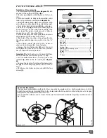
To replace central heating safety valve
If safety valve seating is damaged, it will be neces-
sary to replace safety valve as a complete unit,
repair is not possible.
• Drain down heating circuit of boiler only as de-
scribed previously.
• Disconnect safety valve discharge pipe from
safety valve.
• Remove wire clip securing safety valve to fixing
jig and remove safety valve,
see diagram 10.
• Fit replacement safety valve in reverse order to
removal.
Note
: Apply a small quantity of silicon grease to
the safety valve 'O' ring prior to fitting.
• Open isolating valves on flow and return connec-
tions, refill, vent and pressurise boiler.
• Check for leaks.
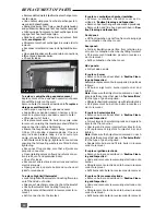
To replace storage vessel safety valve
If safety valve seating is damaged, it will be neces-
sary to replace safety valve as a complete unit,
repair is not possible.
• Drain down hot water circuit of boiler only as de-
scribed previously.
• Disconnect safety valve discharge pipe from
safety valve.
• Remove wire clip securing safety valve to fixing
jig and remove safety valve,
see diagram 10.
• Fit replacement safety valve in reverse order to
removal.
Note
: Apply a small quantity of silicon grease to
the safety valve 'O' ring prior to fitting.
Pla
214
Diagram 10
➜
➜
• Open isolating valve on cold water inlet connec-
tion.
• Check for leaks.
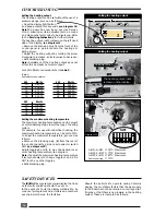
To replace heat exchanger
• Drain down heating circuit of boiler only as de-
scribed previously.
Note:
It is not necessary to drain down entire heat-
ing system to carry out this work.
• Remove combustion chamber cover, as de-
scribed in ‘
Routine Cleaning and Inspection'.
• Disconnect electrical connector from high limit
thermostat.


