43
2000225294A
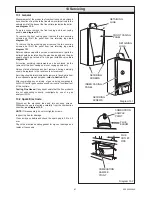
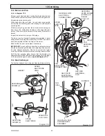
Diagram 13.5
CONDENSATE
DRAIN PIPE
13 Servicing
DOMESTIC HOT WATER
OUTLET COUPLING
12178
CONDENSATE
DRAIN
FIXING
BRACKET
13.5 Condensate Drain
Refer to
diagram 13.5 and 13.6.
Remove condensate drain pipe.
Slide fixing bracket forward and remove, ease condensate
drain down off the inlet connection.
Carefully remove the condense drain taking care not to spill any
water which may be in the unit. As the unit is lifted remove the
flexible connection on the outlet.
Remove the cap at the base of the condense trap.
Remove any solids found.
Remove the strainer and clean.
Remove the float, clean and check it floats.
Flush water through the trap to remove any remaining solids.
Check for any debris in the outlet pipe of the condensate drain
and clean as necessary.
Reassemble and fill the trap with water, refit the condensate
drain.
When refitting the cap ensure that a watertight seal is achieved,
but do not use excessive force.
13.6 Combustion Check.
Once the appliance has been reassembled (apart from the front
and inner casing panels) connect a CO
2
combustion analyser to
the sample
point on the flue elbow, or alternatively to the point
at the base of the flue outlet pipe inside the boiler casing,
see
diagram 13.2.
Turn on the gas service cock,
see diagram 9.2.
With the power off and the appliance cold, unclip the controls
fascia and hinge it down to reveal the potentiometers on the rear
of the User interface,
see diagrams 13.7 and 13.8.
Take care
not to allow the fascia to drop down and damage the wiring.
Turn on the electrical supply.
Ensure external controls are calling for heat. The boiler should
fire automatically.
Allow the boiler to fire for a minimum of 60 seconds and then,
using an electrical screwdriver, rotate the service potentiometer
fully clockwise,
see diagram 13.8.
This will allow the digital
display to indicate the 'flashing' fan speed on the appliance
fascia.
In the fully clockwise position the display should be indicating
the maximum fan speed of the appliance, this should be 54.
Check the CO
2
value, which should be 9.2%
±
0.2%.
Note that with the inner case front panel fitted the
combustion readings will increase slightly to 9.3%
±
0.3%.
If adjustment proves necessary then proceed as follows.
Any adjustment to the gas valve should only be carried out by
a
competant person
.
Refer to
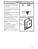
diagram 13.9.
Adjust the maximum rate CO
2
with the throttle to 9.2%. (Rotate
anti-clockwise to increase).
Rotate the service potentiometer fully anti-clockwise. Hold it in
this position for about 5 seconds before rotating the service
potentiometer clockwise to the mid-point or 3 o'clock position.
The fan should reduce to 1300 rpm which will flash '13' on the
LCD display.
Check the CO
2
value, which should be 8.3%
±
0.2%.
If adjustment proves necessary then proceed as follows.
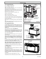
Diagram 13.6
12258
STRAINER
FLOAT
CONDENSE
TRAP
SEAL
CAP
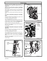
Diagram 13.7
RETAINING
LATCHES
12228
(F24e/F28e SHOWN )
Содержание EnviroPlus F24e
Страница 18: ...18 2000225294A Diagram 5 1 11907 5 Boiler Schematic F24e F28e ONLY ...
Страница 19: ...19 2000225294A 5 Boiler Schematic Diagram 5 1a 12248 BYPASS F28e SB ONLY ...
Страница 49: ...49 2000225294A 14 Fault Finding 12410 Diagram 14 4 ...
Страница 51: ...51 2000225294A 15 Wiring Diagram Diagram 15 1a 12240 F28e SB ONLY ...


