


42
2000225294A
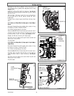
Diagram 13.4
13 Servicing
SECURING
PLATE SCREW
(Slacken pull
forwards
to remove)
FAN
SECURING
PLATE
BURNER
FAN
SEAL
GAS VALVE, FAN
AND SILENCER
ASSEMBLY
GAS PIPE
SECURING
CLIP
GAS VALVE
ELECTRICAL
CONNECTIONS
12185
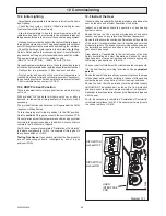
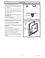
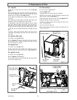
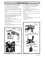
13.3 Burner and Fan
Refer to
diagram 13.4.
Remove spark electrode lead, heating flow thermistor electrical
connections and electrical connections to the fan and gas valve.
Remove gas pipe securing clip.
While supporting the gas valve, fan and silencer assembly,
slacken the fan securing plate screw enough to withdraw the
securing plate.
Carefully swing the gas valve, fan and silencer assembly out
from under the combustion chamber, while supporting the
burner. (Take care as the burner will drop down). Remove the
burner.
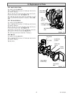
Inspect the burner for any signs of damage.
The burner can be cleaned if necessary by washing in warm
soapy water and rinsing with clean water. DO NOT use wire or
sharp instruments to clean the holes of the burner.
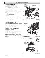
Examine the fan seal and replace if necessary.
IMPORTANT:
Care should be taken when inserting the burner
into the heat exchanger chamber and replacing the gas valve,
fan and silencer assembly. The fan seal must be seated
correctly with the burner before the fan securing plate is refitted.
Refit the fan securing plate, ensure that the dimples are
uppermost and that the fork on the plate engages onto the ledge
on the heat exchanger chamber,
see inset diagram 13.4
.
13.4 Heat Exchanger
The heat exchanger does not require cleaning during servicing.
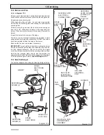
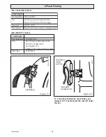
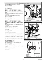
Diagram 13.3
GASKET
SPARK
ELECTRODE
LEAD
SECURING
SCREW (2)
11916
SECURING
SCREW (2)
SPARK GAP
3.5 to 4.5mm
11917
12225
LEDGE
SPARK
ELECTRODE
LEAD
HEATING FLOW
ELECTRICAL
CONNECTIONS
FAN
ELECTRICAL
CONNECTIONS
SPARK
ELECTRODE
Содержание EnviroPlus F24e
Страница 18: ...18 2000225294A Diagram 5 1 11907 5 Boiler Schematic F24e F28e ONLY ...
Страница 19: ...19 2000225294A 5 Boiler Schematic Diagram 5 1a 12248 BYPASS F28e SB ONLY ...
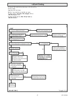
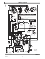
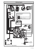
Страница 49: ...49 2000225294A 14 Fault Finding 12410 Diagram 14 4 ...
Страница 51: ...51 2000225294A 15 Wiring Diagram Diagram 15 1a 12240 F28e SB ONLY ...