background image

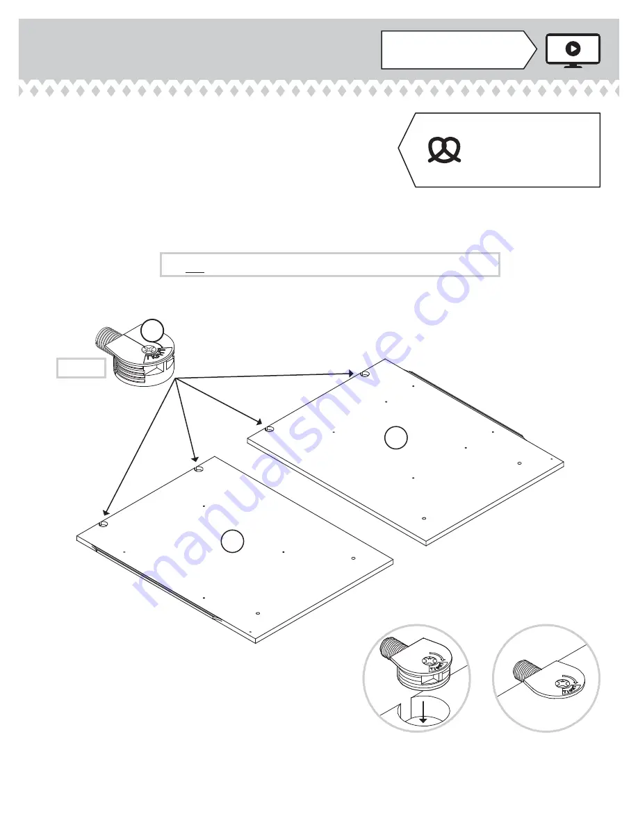
Step 1

Look for this icon. It means a 
video assembly tip is available at 

www.sauder.com/services/tips


å

Assemble your unit on a carpeted fl oor or on the empty 
carton to avoid scratching your unit or the fl oor.


å

To begin assembly, push a SAUDER TWIST-LOCK® 
FASTENER (W) into the large holes in the RIGHT END (A) 
and LEFT END (B). Repeat this step for the BOTTOM (D).

Do not tighten the TWIST-LOCK® FASTENERS in this step.

(11 used)

W

A

B

Some assembly 
(and snacks) required.

408293

www.sauder.com/services

Page 5

Содержание Office Port 408293

Страница 1: ... INSTRUCTION BOOKLET CONTAINS IMPORTANT SAFETY INFORMATION PLEASE READ AND KEEP FOR FUTURE REFERENCE English pg 1 25 Français pg 26 29 Español pg 30 33 Lot 372756 05 20 15 Purchased __________________ Be sure to give us a ring before making any returns 1 800 523 3987 When you re feeling nostalgic for paper Lateral File Office Port Collection Model 408293 ...

Страница 2: ... This time 2 3 3 4 5 25 26 29 30 33 34 35 Table of Contents Part Identification A RIGHT END 1 B LEFT END 1 C TOP 1 D BOTTOM 1 E BACK 1 F BASE 1 G2 UPPER DRAWER FRONT 1 H2 LOWER DRAWER FRONT 1 D61 DRAWER BACK 2 D87 RIGHT DRAWER SIDE 2 D88 LEFT DRAWER SIDE 2 D729 DRAWER BOTTOM 2 M EXTENSION BLOCK 4 N INTERLOCK EXTENSION 1 O BOTTOM MOLDING 1 Z END MOLDING 2 M63 BRACE 2 408293 www sauder com services P...

Страница 3: ...nguish similar parts from each other Use this part identification to help identify similar parts A B C D E F M M M M O Z Z G2 H2 NN M63 D61 D61 D87 D87 D88 D729 D729 D88 N EXTENSION RAIL 4 Q EXTENSION SLIDE 4 R FILE GLIDE 4 6B BACK FILE BRACKET 2 12B HIDDEN CAM 2 1F Hardware Identification EXTENSION SET SHOWN SEPARATED 408293 www sauder com services Page 3 ...

Страница 4: ...ARGE HEAD SCREW 8 KK SILVER 2 FLAT HEAD SCREW 8 GG W TWIST LOCK FASTENER 11 LL GOLD 5 16 FLAT HEAD SCREW 16 Y SLIDE CAM 4 EE DRAWER ACTUATOR 2 BROWN 1 5 8 FLAT HEAD SCREW 2 HH BLACK 1 PAN HEAD SCREW 8 II AA CABINET ACTUATOR 2 NAIL 26 MM 30S BLACK 1 9 16 FLAT HEAD SCREW 10 CAM DOWEL 2 2F FILE BAR 4 T FILE ROD 4 U INTERLOCK TRACK 1 V FILE BRACKET 2 DD 408293 www sauder com services Page 4 ...

Страница 5: ...on the empty carton to avoid scratching your unit or the floor å To begin assembly push a SAUDER TWIST LOCK FASTENER W into the large holes in the RIGHT END A and LEFT END B Repeat this step for the BOTTOM D Do not tighten the TWIST LOCK FASTENERS in this step 11 used W A B Some assembly and snacks required 408293 www sauder com services Page 5 ...

Страница 6: ... FLAT HEAD SCREWS GG å NOTE Be sure to use the first and third holes in the EXTENSION BLOCKS The 1st hole must be 5 1 2 from the end as shown Follow the diagram closely 5 1 2 A B M M M M Notched edge Notched edge SILVER 2 FLAT HEAD SCREW 8 used for the EXTENSION BLOCKS GG 408293 www sauder com services Page 6 ...

Страница 7: ...asten the INTERLOCKEXTENSION N to the RIGHT END A Use two BROWN 1 5 8 FLAT HEAD SCREWS HH Step 3 A N BROWN 1 5 8 FLAT HEAD SCREW 2 used for the INTERLOCK EXTENSION HH 408293 www sauder com services Page 7 ...

Страница 8: ...nsert two CABINET ACTUATORS AA into the holes shown in the EXTENSION BLOCK M Step 4 This pin must insert into the location holes in the EXTENSION BLOCK M A M AA AA AA 408293 www sauder com services Page 8 ...

Страница 9: ...holding the previously completed CABINET ACTUATOR in its location hole å Diagram 5 Remove the INTERLOCK TRACK assembly from Diagram 4 and flip it over before inserting the INTERLOCK TRACK V with CABINET ACTUATORS AA into the groove in the INTERLOCK EXTENSION N Step 5 Be sure the interlock track snaps into each cabinet actuator 5 4 3 2 FLIP OVER 2 1 The interlock system is a safety feature that prev...

Страница 10: ...NSION RAIL turn a SCREW into the hole shown in the enlarged diagram Then slide the innercartridge of the EXTENSION RAIL in to find the other hole that lines up with the hole in the EXTENSION BLOCK Turn a SCREW into this hole Open end Open end Push the black lever in and pull the SLIDE from the RAIL GOLD 5 16 FLAT HEAD SCREW 8 used in this step LL M M M M Q Q Q Q Q R 408293 www sauder com services P...

Страница 11: ...he FASTENER into the hole of the adjoining part NOTE The dowel end of the FASTENER must remain fully inserted in the hole of the adjoining part while locking the FASTENER 2 Tighten the FASTENER with a Phillips screwdriver as tight as possible Dowel end A B D 408293 www sauder com services Page 11 Edge with TWIST LOCK FASTENERS Notched edge Notched edge ...

Страница 12: ...å Fasten the TOP C to the ENDS A and B Tighten four TWIST LOCK FASTENERS Step 8 A B C Unfinished edge 408293 www sauder com services Page 12 ...

Страница 13: ...ed edges of the ENDS A and B å U S Patent No 5 499 886 Step 9 A B Z Z Notched edge Slide the END MOLDING Z onto the notched edge Slide the END MOLDING Z onto the notched edge 408293 www sauder com services Page 13 These surfaces should be even ...

Страница 14: ...å Fasten the BOTTOM MOLDING O to the BOTTOM D Tighten three TWIST LOCK FASTENERS Step 10 These edges must be even D O 408293 www sauder com services Page 14 ...

Страница 15: ...S JJ å NOTE Be sure the BRACKETS are even with the edges of the ENDS and BOTTOM å Fasten the BASE F to the METAL BRACKETS Use four BLACK 9 16 LARGE HEAD SCREWS JJ Step 11 BLACK 9 16 LARGE HEAD SCREW 8 used in this step JJ X X X A B D F S u r f a c e w i t h o u t h o l e s 408293 www sauder com services Page 15 ...

Страница 16: ... all four edges of the BACK E Push on opposite corners of your unit if needed to make it square å Fasten the BACK E to your unit using the NAILS MM Step 12 Do not stand the unit upright without the BACK fastened The unit may collapse Caution NAIL 26 used in this step MM E Notched edge 408293 www sauder com services Page 16 ...

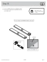
Страница 17: ...end of a CAM DOWEL 2F into each HIDDEN CAM Step 13 Arrow 1F 2F Insert the metal end of the CAM DOWEL into the HIDDEN CAM Arrow Do not tighten the HIDDEN CAMS in this step Don t worry It isn t Rome This can be built in a day 408293 www sauder com services Page 17 M63 M63 ...

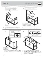
Страница 18: ...eat this step for the other DRAWER The tabs should insert freely into the slots Gently tilt the DRAWER SIDES side to side until the tabs slip into the slots Surface with HIDDEN CAM 1 2 3 4 Be sure the DRAWER BOTTOM inserts into the DRAWER FRONT groove With the palm of your hand tap the DRAWER BOTTOM down into the groove Groove Arrow Maximum 210 degrees Minimum 190 degrees Start each screw a few tu...

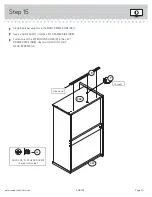
Страница 19: ...SLIDE CAM Y into the LEFT DRAWER SIDE D88 å Fasten one of the EXTENSION SLIDES R to the LEFT DRAWER SIDE D88 Use two GOLD 5 16 FLAT HEAD SCREWS LL Step 15 D87 D88 Open end R Y GOLD 5 16 FLAT HEAD SCREW 4 used in this step LL 2 used 408293 www sauder com services Page 19 ...

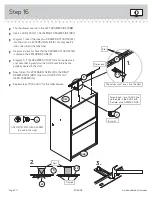
Страница 20: ...e DRAWER ACTUATOR is not seated use your hammer to gently tap the SLIDE until the tabs are properly seated in the slots å Now fasten this EXTENSION SLIDE R to the RIGHT DRAWER SIDE D87 Use two GOLD 5 16 FLAT HEAD SCREWS LL å Repeat steps 15 16 and 17 for the other drawer Step 16 3 Screw head turn CAM to line up the hole in the SLIDE with the hole in the DRAWER SIDE Slot These tabs must insert into...

Страница 21: ...K D61 Use two BROWN 7 16 LARGE HEAD SCREWS KK å Fasten two PULLS BB to the UPPER DRAWER FRONT G2 Use four BLACK 1 PAN HEAD SCREWS II å Repeat this step for the lower drawer Step 17 D61 BB 12B BB DD G2 BLACK 1 PAN HEAD SCREW 8 used for the PULLS II BROWN 7 16 LARGE HEAD SCREW 8 used for the FILE BRACKETS KK 408293 www sauder com services Page 21 ...

Страница 22: ...T through the holes in the FILE BRACKETS 12B and DD through another FILE BAR T and into the FILE GLIDE 6B on the RIGHT DRAWER SIDE D87 å Slide another FILE GLIDE 6B onto the other end of the FILE RODS U then press this FILE GLIDE over the LEFT DRAWER SIDE D88 å Repeat this step for the lower drawer Step 18 D87 D88 T T U U 12B 6B 6B DD 408293 www sauder com services Page 22 ...

Страница 23: ... SLIDES on the drawer with the EXTENSION RAILS on the unit and push the drawer into the unit until the drawer is fully inserted The drawer will push in hard until it is all the way in then it will slide in and out easier Step 19 G2 H2 45 lbs 45 lbs 60 lbs 408293 www sauder com services Page 23 ...

Страница 24: ...the TOP C If the CAM does not fit properly you may need to slightly bend the CAM Step 20 The end of the CAM must be closer to the DRAWER FRONT then the other end of the CAM Turn the key clockwise to lock the drawer The prongs must press into the DRAWER FRONT as you tighten the NUT with the adjustable wrench Cam Screw Nut Washer Almost time to celebrate With a nap 408293 www sauder com services Page...

Страница 25: ... Tighten the SCREW when finished with adjustments å NOTE Please read the back pages of the instruction booklet for important safety information å This completes assembly Clean with your favorite furniture polish or a damp cloth Wipe dry And to celebrate why not share your success story The higher the screw in the oblong hole the higher your drawer front will be The lower the screw the lower the dra...

Страница 26: ... gris sur les schémas de chaque étape pour plus de précision Comparer la Liste de pièces ci dessous avec la PART IDENTIFICATION du manuel en anglais pour vous familiariser avec les pièces avant l assemblage REMARQUE CE MANUEL D INSTRUCTIONS CONTIENT D IMPORTANTES INFORMATIONS RELATIVES À LA SÉCURITÉ À LIRE ET CONSERVER POUR TOUTE RÉFÉRENCE FUTURE Classeur latéral W FIXATION TWIST LOCK 11 X CONSOLE...

Страница 27: ...ble de RAIL DE VERROUILLAGE du Schéma 4 et le retourner avant d insérer le RAIL DE VERROUILLAGE V avec les ACTIONNEURS D ÉLÉMENT AA dans la rainure de l EXTENSION D INTERVERROUILLAGE N ÉTAPE 10 Fixer la MOULURE DE DESSOUS O au DESSOUS D Serrer trois FIXATIONS TWIST LOCK ÉTAPE 7 Fixer les EXTRÉMITÉS A et B au DESSOUS D Serrer quatre FIXATIONS TWIST LOCK Utilisation de la FIXATION TWIST LOCK SAUDER ...

Страница 28: ...DE TIROIR D88 Fixer l une des COULISSES D EXTENSION R au CÔTÉ GAUCHE DE TIROIR D88 Utiliser deux VIS DORÉES TÊTE PLATE 8 mm LL ÉTAPE 14 Insérer un CÔTÉ DE TIROIR D87 et D88 en biseau dans la fente dans chaque extrémité du DEVANT DE TIROIR SUPÉRIEUR G2 Enfiler le FOND DE TIROIR D729 dans les rainures des CÔTÉS DE TIROIR D87 et D88 et du DEVANT DE TIROIR SUPÉRIEUR G2 Fixer l ENTRETOISE DE TIROIR M63 ...

Страница 29: ...s Enfiler les GUIDES POUR DOSSIERS U à travers une TRINGLE POUR DOSSIERS T à travers les trous dans les CONSOLES POUR DOSSIERS 12B et DD à travers autre TRINGLE POUR DOSSIERS T et dans le GUIDE POUR DOSSIERS 6B situé sur le CÔTÉ DROIT DE TIROIR D87 Enfiler une autre ARMATURE POUR DOSSIERS 6B sur l autre extrémité des GUIDES POUR DOSSIERS U et appuyer cette ARMATURE POUR DOSSIERS sur le CÔTÉ GAUCHE D...

Страница 30: ...l folleto en inglés para familiarizarse con Las partes de ensamblaje NOTA ESTE FOLLETO DE INSTRUCCIONES CONTIENE INFORMACIÓN IMPORTANTE SOBRE LA SEGURIDAD POR FAVOR LEA Y GUÁRDELO PARA REFERENCIA EN EL FUTURO LISTA DE PARTES ITEM DESCRIPCIÓN CANTIDAD Archivero Lateral Y EXCÉNTRICO DE CORREDERA 4 AA ACTUADOR DE GABINETE 2 BB TIRADOR 4 DD MÉNSULA DE ARCHIVERO 2 EE ACTUADOR DE CAJÓN 2 FF PAQUETE DE C...

Страница 31: ... FONDO D PASO 10 Fije la MOLDURA DE FONDO O al FONDO D Apriete tres SUJETADORES TWIST LOCK PASO 9 Deslice las MOLDURAS DE EXTREMO Z sobre los bordes con muesca de los EXTREMOS A y B Patente EE UU No 5 499 886 PASO 8 Fije el PANEL SUPERIOR C a los EXTREMOS A y B Apriete cuatro SUJETADORES TWIST LOCK PASO 5 Gráfico 1 Mida 51 mm de un extremo del CARRIL DE UNIÓN V Coloque el CARRIL DE UNIÓN como se mu...

Страница 32: ...RDO DE CAJÓN D88 Fije una de las CORREDERAS DE CAJÓN R al LADO IZQUIERDO DE CAJÓN D88 Utilice dos TORNILLOS DORADOS DE CABEZA PERDIDA de 8 mm LL PASO 14 Inserte un LADO DE CAJÓN D87 y D88 en ángulo en el encajeen cada extremo de la CARA DE CAJÓN SUPERIOR G2 Deslice el FONDO DE CAJÓN D729 en las ranuras de los LADOS DE CAJÓN D87 y D88 y de la CARA DE CAJÓN SUPERIOR G2 Fije la RIOSTRA DE CAJÓN M63 a...

Страница 33: ...EVA PASO 19 Cuidadosamente ponga la unidad en posición vertical Para insertar un cajón dentro de la unidad alinee las CORREDERAS DE EXTENSIÓN sujetadas al cajón con los RIELES DE EXTENSIÓN sujetados a la unidad y empuje el cajón dentro de la unidad hasta que el cajón esté completamente insertado El cajón mueve con dificultad hasta que se inserte completamente dentro de la unidad después deslizará f...

Страница 34: ...u de dommage matériel Le classeur risque de se renverser si on ne fait pas preuve de prudence pour le déplacer par dessus les obstacles ou d une surface de sol à une autre par exemple d un plancher à moquette Relever le classeur de manière à dégager les roulettes de tour obstacles ou tout changement abrupt dans la surface du sol Il est dangereux utiliser un meuble que n est pas conçu pour supporte...

Страница 35: ... ainsi qu une preuve d achat Les pièces de rechange seront garanties uniquement pendant la période restante de la garantie originale SAUDER NE SERA EN AUCUN CAS RESPONSABLE de TOUT DOMMAGE ACCESSOIRE OU CONSÉCUTIF DE TOUTE SORTE et lesdits dommages sont EXCLUS DE LA PRÉSENTE GARANTIE à savoir perte d utilisation démontage transport main d œuvre ou dommages matériels sur ou à proximité du produit C...

Страница 36: ...ld true to his core values of innovation integrity servanthood and stewardship Sauder products are made with environmentally responsible materials and world class manufacturing processes Our 2 000 dedicated employees in Archbold Ohio along with our global manufacturing partners are committed to providing you furniture with great value style and quality From our family to you Enjoy Kevin J Sauder P...

Отзывы: