SATELLINE-M3-TR3,
–
TR4 and -R4
Integration Guide, Version 3.0
18
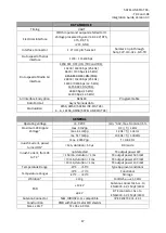
Weight
18g
Test condition
𝑉
𝐶𝐶
= 4.0 V and
𝑇
𝐴
= 25 °C
1
According to EN 300 113-1 V.1.7.1 measurement setup
2
The measured average of a sample of 19 M3-TR3 modules
3
Higher values exceed the -36 dBm spurious limit at the antenna e.g. EN 300 113-1 requirement.
4
Measured using Agilent 1147B current probe and TTi TSX1820P DC power supply
5
If 1 W output power is wanted then 4.0 V is the minimum DC voltage
6
Functional operation is guaranteed in all directions xyz
3.1
Absolute maximum ratings
Absolute maximum ratings for voltages (* on different pins are listed in the following table.
Exceeding these values will cause permanent damage to the module.
Parameter
Min
Max
Voltage at VCC_IN
-0.3 V
+5 V
Voltage at ENA_MOD
-0.3 V
+6 V
Voltage at VCC_IO
-0.5 V
3.75 V
Voltage at digital inputs (except ENA_MOD)
-0.5 V
3.75 V
Voltage at digital outputs (when no power is applied to unit)
-0.5 V
3.75 V
Antenna port power
n.a.
+14 dBm
Antenna port DC voltage
-10V
+10V
Table. Absolute maximum ratings of module. (* All voltages are referenced to GND
3.2
DC electrical specifications
Over recommended operating conditions
Parameter
Condition
Min
Max
Units
VCC_IN
4.0V is considered nominal
4.0V
1
N5%
V
ENA_modem, Vlow
0
0.4
V
ENA_modem, Vhigh
0.9
VCC_IN
V
Logic input, Vlow
1.8V<VCC_IO<3.3V
-0.3
<0.35*VCC_IO
V
Logic input, Vhigh
1.8V<VCC_IO<3.3V
0.65*VCC_IO
3.6
V
Logic output, Vlow
1.8V<VCC_IO<3.3V
-
0.4
V
Logic output, Vhigh
1.8V<VCC_IO<3.3V
VCC_IO-0.4
3.6
V
Logic output, max
current
All logic output except
STAT pin.
-
4
mA
Logic output, max
current, STAT pin
-
12
mA
1
Minimum voltage if the maximum TX output power (1W/50
Ω
load) is wanted. Meets the ETSI
requirements on given operating voltage range.

