SATELLINE-M3-TR3,
–
TR4 and -R4
Integration Guide, Version 3.0
11
modulates and demodulates, encodes and decodes the data and sends the received data
payload to the DTE port. The DTE interface is used to provide power to the module and
communicate with the module.
Available product variants can be viewed from SATEL WEB sites.
1.3
DTE connector
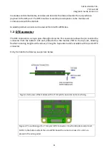
The DTE connector is a 20-pin pass-through connector. This connector allows the pin to enter the
connector from the bottom side and protrude thru the module PCB to the top side, allowing
flexible mounting heights with various pin lengths. Separate models available with top side DTE
connector.
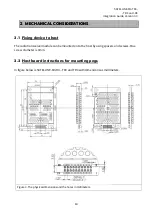
Entry from bottom of device, see picture below.
Figure 1. Side view of the module with 1.27mm pitch connector and screw fixing.
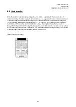
Figure 2. Pin numbering of 1.27 mm pitch DTE connector. View from bottom side of unit.
NOTE! In the bottom side of the actual PCB board the numeric values of 1 and 2 are
placed in the wrong order.


