ezPAC™
SA300 Series
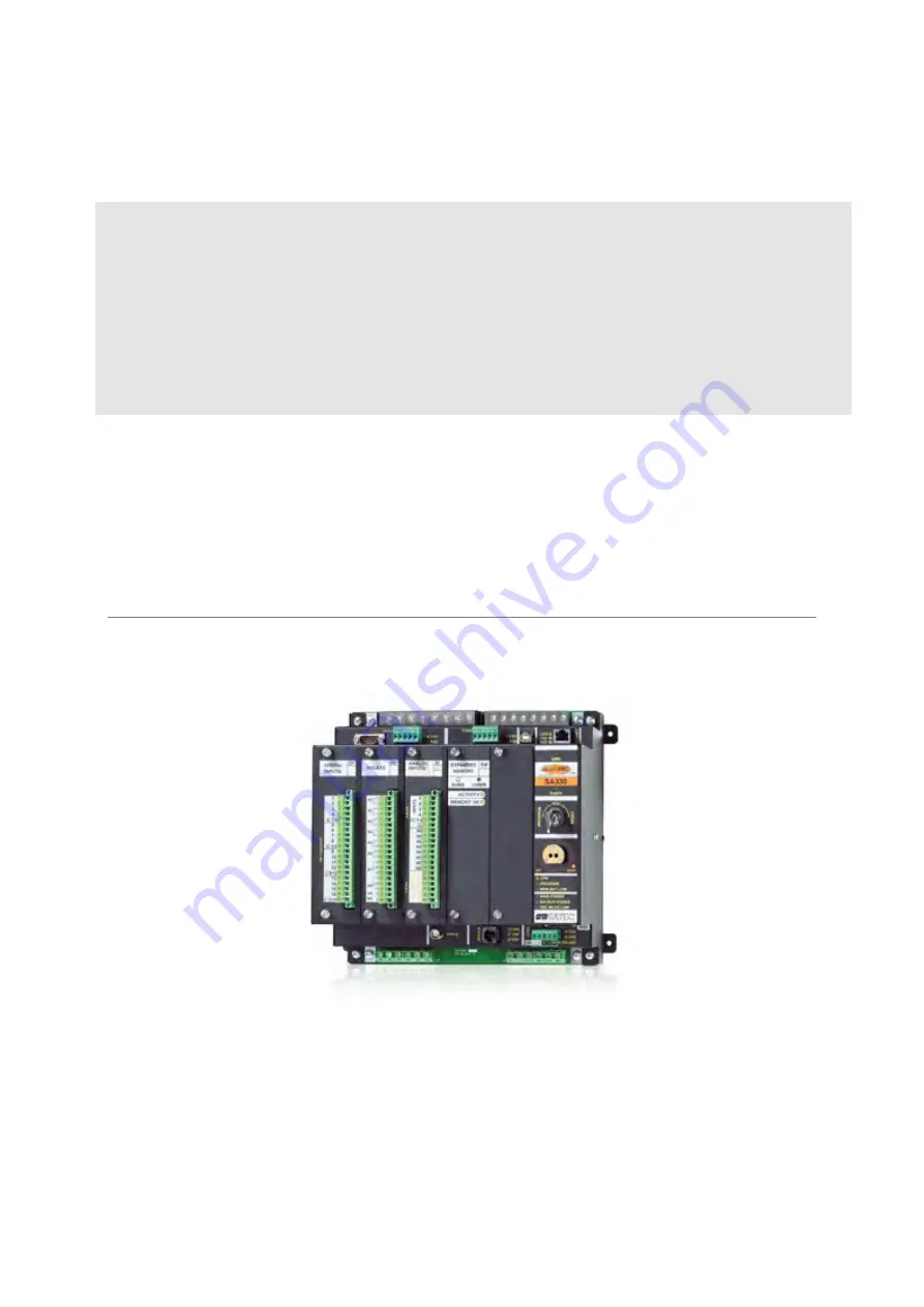
SUBSTATION AUTOMATION UNIT
SA310/SA320/SA330
Installation Manual
BG0325 Rev. D
Страница 1: ...ezPAC SA300 Series SUBSTATION AUTOMATION UNIT SA310 SA320 SA330 Installation Manual BG0325 Rev D ...
Страница 2: ...orming installation and take note of the following precautions 1 Ensure that all incoming AC power and other power sources are turned OFF before performing any work on the instrument Failure to do so may result in serious or even fatal injury and or equipment damage 2 Before connecting the instrument to the power source check the labels on the side of the instrument to ensure that your instrument ...
Страница 3: ...About This Manual 1 1 2 About The SA300 1 Chapter 2 Installation 4 2 1 Mechanical Installation 4 2 2 Electrical Installation 8 2 3 Location of Modules 25 Chapter 3 Communications 26 Chapter 4 Changing the Battery 32 Appendix Technical Specifications 33 ...
Страница 4: ...gement keeping the standard 150A current inputs for fault recording Features The SA300 combines in a single enclosure Digital Fault Recorder onboard fault detector programmable fault thresholds and hysteresis up to 150 Amps fault currents zero sequence currents and volts current and volt unbalance up to 48 external digital triggers from tripping protection relays ready for use fault reports fault ...
Страница 5: ...EC or 20A ANSI input currents to 150 Amps fault currents Optional second set of four isolated current inputs 10A IEC or 20A ANSI input currents for precise energy metering DC voltage input up to 300VDC for monitoring the station battery Digital and Analog I O Options The SA300 has five I O expansion slots for removable plug in I O modules DI Digital inputs 16 or 32 optically isolated inputs per mo...
Страница 6: ...e RMS and harmonics measurements status indication parameters and perform basic setup operations when installing and servicing the device The RGM is equipped with a color graphics LCD display and has extensive dialog capabilities allowing the user to view different fault and power quality information in a graphical form such as waveforms harmonic spectrum phasor and data trends review latest fault...
Страница 7: ... 8 6 3 2 5 8 6 3 9 6 5 2 5 8 6 3 J3 J12 6 5 3 2 COM2 COM1 Tx Rx Tx Rx CURRENT INPUTS I I I I 1 2 3 IRIG B VOLTAGE INPUTS PLUG IN MODULE PLUG IN MODULE PLUG IN MODULE 4 MODEM V1 1 V2 V3 17 14 11 4 7 1 RS 232 1 1 JP3 V N V 4 4 V 4N 17 14 11 17 14 11 4 J10 1 1 2 17 18 19 20 12 15 14 16 13 11 RDM P SUPPLY 3 4 J2 5 6 J14 4 7 1 RS 422 RS 485 RS 422 RS 485 4 7 1 J1 4 7 8 2 3 J11 4 10 9 7 1 4 1 1 2 3 4 5 ...
Страница 8: ...Chapter 2 Installation 5 Figure 2 1b Mounting ...
Страница 9: ...Chapter 2 Installation 6 PULL OUT SLOW LY BEFORE USE BATTERY LITHIUM AA 3 6 VOLTS View from top BATTERY AA ezPAC ezPAC View from side 03 07009 Figure 2 1c Activating the Battery ...
Страница 10: ...nected to the communication connector of the SA300 unit as shown in Figure 2 2 12V 12V COM COM 2 3 4 5 6 7 1 2 1 NC NC 5 4 3 6 7 GREEN RED BLACK WHITE 12V COM COM 12V 1 2 3 4 5 3 5 4 12 02 04035 DXF ezPAC RDM SA300 UNIT ezPAC Figure 2 2 ezPac RDM Connection ...
Страница 11: ...an 2 mm2 14 AWG 2 2 4 Voltage Inputs SA300 models have 3 AC Y connected voltage inputs of 690V phase to phase and neutral and one separate isolated AC voltage input of 400V 2 2 5 Wiring Configurations For models SA310 SA320 use any of the seven wiring configurations shown in Figures 2 3 2 4 2 5 2 6 2 7 2 8 or 2 9 for model SA330 use any of the four wiring configurations shown in Figures 2 5a 2 6a ...
Страница 12: ...R1 J7 JP3 J2 J3 J1 J11 J5 RS 232 RS 422 RS 485 RS 422 RS 485 RS 485 1 5 6 9 1 2 3 4 5 1 2 3 4 5 5 4 3 2 1 4 1 2 1 3 4 1 8 1 2 3 4 5 6 7 8 1 2 3 4 5 6 L N RDM P SUPPLY INPUTS GROUND MAIN POWER SUPPLY SW2 SW1 125 220V DC OR 120 230V AC DC MEASUREMENT V3 N V V V J14 J12 CT SA320 150A SA310 150A NOT CONNECTED Switches 125 220V DC 02 04012 1 2 3 4 5 6 1 2 3 4 5 6 7 8 Figure 2 3 SA310 SA320 Three Wire D...
Страница 13: ...MAIN POWER GROUND MEASURE VDC BACKUP POWER SUPPLIES MAIN N 2 125 220V DC J10 1 N L SW2 3 4 L 5 6 OR 120 230V AC 125 220V DC NOT CONNECTED 8 1 RS 485 ETHERNET RS 422 485 MODEM JP3 1 4 J1 COM2 7 8 Rx Tx 1 2 4 Rx 3 Tx 5 1 J2 COM3 3 P SUPPLY 4 RDM 5 3 2 4 USB J11 2 3 2 4 1 6 5 7 1 J5 8 LOAD DC LINE 1 LINE 3 LINE 2 B C A CURRENT INPUTS SA320 150A SA310 150A J14 J12 Figure 2 4 SA310 SA320 Four Wire WYE ...
Страница 14: ...UND MEASURE VDC BACKUP POWER SUPPLIES MAIN N 2 125 220V DC J10 DC 1 N L SW2 3 4 L 5 6 OR 120 230V AC 125 220V DC NOT CONNECTED 8 1 RS 485 ETHERNET RS 422 485 MODEM JP3 1 4 J1 COM2 7 8 4 Rx Tx 1 2 4 Rx 3 Tx 5 1 J2 COM3 3 P SUPPLY 4 RDM 5 3 2 4 USB J11 2 3 2 4 1 6 5 7 Switches Shorting 1 J5 8 LOAD B LINE 2 LINE 3 C LINE 1 A CURRENT INPUTS SA320 150A SA310 150A J14 J12 Figure 2 5 SA310 SA320 Four Wir...
Страница 15: ...OUND MEASURE VDC BACKUP POWER SUPPLIES MAIN N 2 125 220V DC J10 DC 1 N L SW2 3 4 L 5 6 OR 120 230V AC 125 220V DC 8 1 RS 485 ETHERNET RS 422 485 MODEM JP3 1 4 J1 COM2 7 8 4 Rx Tx 1 2 4 Rx 3 Tx 5 1 J2 COM3 3 P SUPPLY 4 RDM 5 3 2 4 USB J11 2 3 2 4 1 6 5 7 Switches Shorting 1 J5 8 LOAD B LINE 2 LINE 3 C LINE 1 A 8 I I 5 I 6 I 7 K L K L K L K L SA330 20A INPUTS CURRENT RELAY CTs METER CTs J14 J12 Figu...
Страница 16: ... Rx 4 5 6 12V GND RDM SUPPLY MAIN POWER GROUND MEASURE VDC BACKUP POWER SUPPLIES MAIN N 2 125 220V DC J10 DC 1 N L SW2 3 4 L 5 6 OR 120 230V AC 125 220V DC 8 1 RS 485 ETHERNET RS 422 485 MODEM JP3 1 4 J1 COM2 7 8 Rx Tx 1 2 4 Rx 3 Tx 5 1 J2 COM3 3 P SUPPLY 4 RDM 5 3 2 4 USB J11 2 3 2 4 1 6 5 7 1 J5 8 LOAD CURRENT INPUTS SA320 150A SA310 150A J14 J12 Figure 2 6 SA310 SA320 Three Wire Open Delta Conn...
Страница 17: ...PPLY MAIN POWER GROUND MEASURE VDC BACKUP POWER SUPPLIES MAIN N 2 125 220V DC J10 DC 1 N L SW2 3 4 L 5 6 OR 120 230V AC 125 220V DC 8 1 RS 485 ETHERNET RS 422 485 MODEM JP3 1 4 J1 COM2 7 8 Rx Tx 1 2 4 Rx 3 Tx 5 1 J2 COM3 3 P SUPPLY 4 RDM 5 3 2 4 USB J11 2 3 2 4 1 6 5 7 1 J5 8 LOAD 5 I 7 I K K L L INPUTS SA330 20A CURRENT SA330 150A INPUTS CURRENT RELAY CTs METER CTs J14 J12 Figure 2 6a SA330 Three...
Страница 18: ...MEASURE VDC BACKUP POWER SUPPLIES MAIN N 2 125 220V DC J10 DC 1 N L SW2 3 4 L 5 6 OR 120 230V AC 125 220V DC NOT CONNECTED 8 1 RS 485 ETHERNET RS 422 485 MODEM JP3 1 4 J1 COM2 7 8 Rx Tx 1 2 4 Rx 3 Tx 5 1 J2 COM3 3 P SUPPLY 4 RDM 5 3 2 4 USB J11 2 3 2 4 1 6 5 7 Switches Shorting 1 J5 8 LINE 1 LINE 3 LINE 2 B C A LOAD CURRENT INPUTS SA320 150A SA310 150A J14 J12 Figure 2 7 SA310 SA320 Four Wire Wye ...
Страница 19: ...WER SUPPLIES MAIN N 2 125 220V DC J10 DC 1 N L SW2 3 4 L 5 6 OR 120 230V AC 125 220V DC 8 1 RS 485 ETHERNET RS 422 485 MODEM JP3 1 4 J1 COM2 7 8 Rx Tx 1 2 4 Rx 3 Tx 5 1 J2 COM3 3 P SUPPLY 4 RDM 5 3 2 4 USB J11 2 3 2 4 1 6 5 7 Switches Shorting 1 J5 8 LINE 1 LINE 3 LINE 2 B C A LOAD K K L L K L INPUTS SA330 20A CURRENT SA330 150A INPUTS CURRENT 5 I I 6 7 I RELAY CTs METER CTs J14 J12 Figure 2 7a SA...
Страница 20: ...L N N MAIN POWER SUPPLIES BACKUP VDC MEASURE GND 12V RS 422 485 INPUT VOLTAGE IRIG B RS 422 485 J7 MODEM J10 JP3 P SUPPLY 4 1 COM3 J2 5 RDM 3 4 RS 485 3 4 2 1 RDM 8 Rx J1 2 1 Tx 6 NOT CONNECTED 3 J11 5 3 4 Rx Tx 1 2 USB 2 1 4 5 ETHERNET 1 7 8 J5 RS 232 COM1 JDR1 5 3 Tx 1 J3 2 1 Tx 3 1 2 Rx 4 5 Rx 4 5 COM2 6 7 8 6 9 CURRENT INPUTS SA320 150A SA310 150A J14 J12 Figure 2 8 SA310 SA320 Three Wire Open...
Страница 21: ...LIES BACKUP VDC MEASURE GND 12V RS 422 485 INPUT VOLTAGE IRIG B RS 422 485 J7 MODEM J10 JP3 P SUPPLY 4 1 COM3 J2 5 RDM 3 4 RS 485 3 4 2 1 RDM 8 Rx J1 2 1 Tx 6 3 J11 5 3 4 Rx Tx 1 2 USB 2 1 4 5 ETHERNET 1 7 8 J5 RS 232 COM1 JDR1 5 3 Tx 1 J3 2 1 Tx 3 1 2 Rx 4 5 Rx 4 5 COM2 6 7 8 6 9 K L K K L L INPUTS SA330 20A CURRENT 6 I 5 I I 7 SA330 150A INPUTS CURRENT RELAY CTs METER CTs J14 J12 Figure 2 8a SA3...
Страница 22: ...JDR1 COM1 RS 232 5 1 1 RS 422 485 IRIG B J7 4 Tx J3 2 Rx 1 Tx 3 3 2 5 Rx 4 5 6 12V GND RDM SUPPLY GROUND MEASURE VDC BACKUP POWER SUPPLIES MAIN N 2 125 220V DC J10 DC 1 N L SW2 3 4 L 5 6 OR 120 230V AC 125 220V DC 8 1 RS 485 ETHERNET RS 422 485 MODEM JP3 1 4 J1 COM2 7 8 Rx Tx 1 2 4 Rx 3 Tx 5 1 J2 COM3 3 P SUPPLY 4 RDM 5 3 2 4 USB J11 2 3 2 4 1 6 5 7 1 J5 8 LOAD 3 2 1 CURRENT INPUTS SA320 150A SA31...
Страница 23: ... terminals are internally connected together in 32 DI variant the module has 8 independent isolated circuits containing 4 inputs with one common terminal Dry Contacts 02 04024 Ez PAC C 1 4 C 9 12 C 5 8 C 13 16 8 16 13 15 14 10 12 11 9 DRY CONACTS 4 7 5 6 1 2 3 DIGITAL INPUTS DI 1 2 3 4 DRY CONACTS 20 19 11 15 16 18 17 12 14 13 3 7 8 10 9 4 6 5 2 1 14 13 12 11 1 01 12025 SA300 Figure 2 10 16 DI Con...
Страница 24: ...250V DC LOAD LOAD LOAD LOAD LOAD LOAD LOAD LOAD 14 12 13 11 10A FUSE 1 FUSE 2 10A 1 SA300 02 04025 125V DC 120V DC Figure 2 12 16 DI Digital Input Connection for Wet Contacts Group B 1 2 3 4 Group A 11 12 13 14 CM3a 16 17 18 19 CM4a LOAD LOAD LOAD LOAD 6 7 8 9 LOAD LOAD LOAD LOAD 1 2 3 4 11 12 13 14 CM3b 16 17 18 19 CM4b LOAD LOAD LOAD LOAD 6 7 8 9 LOAD LOAD LOAD LOAD CM1b CM2b CM1a CM2a Fuse1 10A...
Страница 25: ... pulsing as shown in Figure 2 14 and 15 For ratings see Appendix Technical Specifications 02 04023 10A FUSE 1 RELAYS K1 K2 K3 K4 K5 K6 K7 K8 NC NC 1 2 3 4 5 6 7 8 9 10 11 12 13 14 15 16 17 18 19 20 RO 20 10 19 14 17 18 16 15 12 13 11 5 7 8 9 6 3 4 1 2 LOAD LOAD LOAD 120 230V AC OR 125V DC LINE N SA300 Figure 2 14 8 DO Relays Connection Figure 2 15 16 DO Relays Connection Relays 1 6 Form A Relays 7...
Страница 26: ... 1 mA and 1 mA current loop load of up to10 kOhm as shown in Figure 2 16 ANALOG INPUT S OUT PUT S 1 2 3 4 CI 1 4 NC 1 2 3 4 CO 1 4 INPUT S OUT PUT S AI AO NC NC NC NC NC NC NC 4 20mA 4 20mA 1 2 3 4 5 6 7 8 9 10 11 12 13 14 15 16 17 18 19 20 02 04022 Ez PAC SENSOR 2 SENSOR 1 SENSOR 3 SENSOR 4 OUTPUT 1 LOAD OUTPUT 2 OUTPUT 4 OUTPUT 3 INPUT 1 INPUT 2 INPUT 4 INPUT 3 LOAD LOAD LOAD 1 S A300 01 12023 F...
Страница 27: ... one DC voltage input which can be used for measuring of substation storage battery voltage see Figure 2 17a or for measuring unit power supply voltage see Figure 2 17b Copper wiring 1 5 2 5 mm 2 15 13 AWG should be used Figure 2 17 a and b DC Voltage Measurement Input Connection ...
Страница 28: ...unication Network Connection RS 422 RS 485 2 3 Location of Modules The 5 slots for input output modules are used as follows Slots from left to right Digital Inputs Relays Analog Inputs Outputs The standard order is one of each of these modules If an additional module is ordered it is placed next to its kind and the subsequent modules are moved to the right For example If an additional Relay module...
Страница 29: ...Chapter 3 Communications 26 Chapter 3 Communications 3 Communications Figure 3 1 RS 232 RS 422 RS 485 Terminal Blocks ...
Страница 30: ... Connections RS 232 Figure 3 2 RS 232 Hardware Handshaking Connection 9 pin Figure 3 3 RS 232 Hardware Handshaking Connection 25 pin Figure 3 4 RS 232 Simple 3 wire Connection 9 pin female Figure 3 5 RS 232 Simple 3 wire Connection 25 pin ...
Страница 31: ...Chapter 3 Communications 28 External Modem Connections Figure 3 6 RS 232 Simple 3 wire Connection 9 pin male Figure 3 7 RS 232 Simple 3 wire Connection 9 pin Initialization String ATS0 1 D0 K0 W0 ...
Страница 32: ...Chapter 3 Communications 29 Computer Connections RS 422 RS 485 Figure 3 8 RS 422 Multidrop Connection 25 pin PC Port Figure 3 9 RS 485 Multidrop Connection 25 pin PC Port ...
Страница 33: ...Chapter 3 Communications 30 Figure 3 10 RS 422 Multidrop Connection 9 pin PC Port Figure 3 11 RS 485 Multidrop Connection 9 pin PC Port ...
Страница 34: ...Chapter 3 Communications 31 Figure 3 12 RS 485 Multidrop Connection 9 pin PC Port Figure 3 13 RS 485 Multidrop Connection 25 pin PC Port ...
Страница 35: ...n the battery compartment turning counter clockwise 2 Remove the battery cover and the battery 3 Replace the battery with the plus towards the outside and close the compartment IMPORTANT Use an AA lithium 3 6 volt battery In order not to lose data stored in the memory use PAS to upload data see SA300 Operation Manual Chapter 12 to a PC BEFORE changing the battery OR make sure you change the batter...
Страница 36: ...galvanically isolated Option 120 230 VAC 110 220 VDC Rated input 85 265VAC 50 60 Hz 88 290VDC Burden 20W 12 VDC Option Rated input 9 6 19 VDC 24 VDC Option Rated input 19 37 VDC 48 VDC Option Rated input 37 72 VDC Input Ratings AC Voltage Inputs V1 V2 V3 VN Operating Range 690VAC line to line 400VAC line to neutral Direct input and input via PT up to 828VAC line to line up to 480VAC line to neutra...
Страница 37: ...d 20A RMS continuous 250A for 1 second Wire Size 12 AWG 1 5 to 3 5 mm 2 Terminals Pitch 10 mm Input via CT with 1A secondary Operating Range continuous 4A RMS ANSI C12 20 or 2A RMS IEC687 Burden 0 02 VA Overload Withstand 4A RMS continuous 50A for 1 second Wire Size 12 AWG 1 5 to 3 5 mm 2 Terminals Pitch 10 mm VDC Voltage Input Operating Range 2 290 VDC Burden 0 2 W Accuracy 0 5 Galvanic Isolation...
Страница 38: ...hm closed input resistance 10kOhm Wire Size 12 AWG up to 2 5 mm 2 Terminals Pitch 5 mm 32 DI optically isolated 4x8 group wet contact sensing External Power Supply 24 VDC Wire Size 12 AWG up to 2 5 mm 2 Terminals Pitch 5 mm 32 DI optically isolated 4x8 group wet contact sensing External Power Supply 48 VDC Wire Size 12 AWG up to 2 5 mm 2 Terminals Pitch 5 mm 32 DI optically isolated 4x8 group wet ...
Страница 39: ...tor Type DB9 male Serial EIA RS 422 RS 485 optically isolated port Connector Type removable captured wire 5 terminals Wire Size up to 12 AWG up to 2 5 mm 2 Baud Rate up to 115 200 bps Supported Protocols Modbus RTU ASCII DNP 3 0 COM2 Serial EIA RS 422 RS 485 optically isolated port Connector type removable captured wire 5 terminals Wire Size up to 12 AWG up to 2 5 mm 2 Baud Rate up to 115 200 bps ...
Страница 40: ... 3 0 Real time Clock Accuracy maximum error 15 seconds per month 25 C IRIG B Port Optically isolated IRIG B port Time code signal unmodulated pulse width coded Level unbalanced 5V Connector Type BNC Recommended cable 51Ohm low loss RG58A U Belden 8219 or equivalent TNC connector Recommended GPS time code generator Masterclock GPS 200A Log Memory Standard onboard memory 4 Mbytes Plug in expansion m...
Страница 41: ... Harmonized standards to which conformity is declared EN55011 1991 EN50082 1 1992 EN61010 1 1993 A2 1995 ANSI C37 90 1 1989 Surge Withstand Capability SWC EN50081 2 Generic Emission Standard Industrial Environment EN50082 2 Generic Immunity Standard Industrial Environment EN55022 1994 Class A EN61000 4 2 ENV50140 1983 ENV50204 1995 900MHz ENV50141 1993 EN61000 4 4 1995 EN61000 4 8 1993 ...
Страница 42: ... 0 36 PT CT 120V 1 2 PT CT 690V 0 2 0 002 0 002 PF 0 5 and c 0 to 2 000 000 kVA Power factor 1 000 0 35 PF 0 5 I 2 FSI 0 999 to 1 000 Frequency 0 02 40 00 Hz to 70 00 Hz Total Harmonic Distortion THD V I Vf If 999 9 1 5 0 2 THD 1 FS V I 10 FSV FSI 0 to 999 9 Total Demand Distortion TDD 100 1 5 TDD 1 FS I 10 FSI 0 to 100 Active energy Import Export Class 0 2 ANSI C12 20 1998 Current class 20 Class ...
Страница 43: ...oltage If fundamental current Notes 1 Accuracy is expressed as percentage of reading percentage of full scale 1 digit This does not include inaccuracies introduced by the user s potential and current transformers Accuracy calculated at 1 second average 2 Specifications assume voltage and current waveforms with THD 5 for kvar kVA and PF reference operating temperature 20 C 26 C 3 Measurement error ...