Chapter 3 Operating the ETC ONE PLUS
ETC I Communication Setup
ETC ONE PLUS Network Communicator
15
The TCP server can be accessed via a local Ethernet network or via Cellular
Internet connection using 3G cellular module through COM2 port.
ETC I Communication Setup
To configure the ETC I, press <PROG> button for 3 sec during device power
ON, until the <PROG> yellow LED s turned ON. Entering to programming
mode enables the user to configure the ETC I setup and/or to update the
firmware using the PAS Flash Downloader.
The <PROG> mode state forces the COM1 to be in MODBUS “Slave” mode
to enable device configuration with PAS through COM1 (MODBUS RTU).
To exit the programming mode dis-energize the device power and reenergize
it back. Make sure the yellow <PROG> Led is turned OFF.
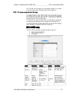
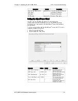
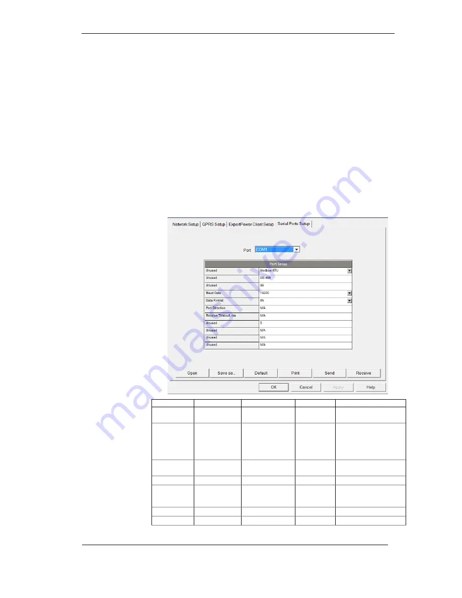
ETC I COM1 setup
The ETC I COM1 port shall be configured as follows using PAS
™
:
1.
Select Communication Setup
2.
Select Serial Ports Setup
3.
COM1 setup
Label
Parameter
Options
Default
Description
Protocol
Communicatio
ns protocol
MODBUS RTU, MODBUS
RTU
The communications
protocol for the port
Interface
Port interface
RS485
RS485, RS232,
Modem,
GSM/GPRS,
RF
RS485
Not changeable;
Device
Address
Device
address
MODBUS:1-247
1
MODBUS Master
device address
Baud rate
Baud rate
2.4-115.2 kbps
19.2 kbps
The port baud rate
Data/Prty
Data format
and parity
7E, 8N, 8E
8N
7E data format should
not be used with the
Modbus RTU protocol
CTS
Clear to send
NA
RTS
Ready to send NA


