11/99
7 - 10
DS 3.401
COMMISSIONING
WARNING -
WHEN ACTUATOR IS OPERATING BEWARE OF TRAPPING
FINGERS ETC.
BEFORE SWITCHING ON POWER SUPPLY:
ALM and ALX Actuators
1.
Check that all control equipment is correctly located and fitted.
2.
Check ambient temperature conditions.
3.
Check that actuator has been correctly assembled to valve, up to
the stage when electrical power is called for.
4.
Remove terminal cover and check that all control circuit wiring is
correct and in accordance with the overall control system wiring
diagram. Check that the electrical supply voltage is correct.
5.
Note: Wiring errors not only cause malfunctions; they may also
damage controllers and/or actuators.
6.
Replace terminal cover. Set manual override push button to 'Auto'
position.
7.
Now switch on power supply.
8.
Check that the actuator functions correctly by operating the
controlling switch or adjusting the controller set value above and
below the temperature (or humidity) currently existing at the sensor
(or simulated). This must be within the scale limits.
If the actuator forms part of a multi-stage system in which several
actuators operate in sequence, wait until the appropriate stage is
reached.
9.
Whilst checking actuator travel over full stroke of valve, run
actuator to fully retracted position. Select self-adhesive indication
scale to match valve stroke, from set of four scales provided. Fix
scale along outside edge of actuator mounting bracket, in position
where it will be most clearly visible, lining up top edge of anti-
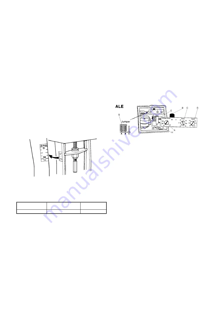
rotation plate on actuator spindle with position '0' on scale (Fig.7).
10. If auxiliary switches are fitted, remove terminal cover to check for
correct operation and switching functions. Replace terminal cover.
ALM, ALX WIRING PRECAUTIONS
WARNING -
ALM ACTUATORS AND AUXILIARY SWITCHES (WHERE FITTED)
ARE AT MAINS POTENTIAL. OBSERVE LOCAL WIRING
REGULATIONS, EARTHING REQUIREMENTS AND ALL USUAL
SAFETY PRECAUTIONS.
* When wiring to BAS outstations refer to the appropriate outstation
data sheet for the wiring precautions.
For longer lengths, increase cable size and observe max. resistance.
Screen feedback wiring, or use MICC or run in a separate conduit,
when applicable.
Caution
Do not connect ALM or ALX actuators in parallel.
ALE Actuators
BEFORE SWITCHING ON POWER SUPPLY:
•
Check that all control equipment is correctly located and fitted.
•
Check ambient temperature conditions.
•
Check that actuator has been correctly assembled to valve, up to the
stage when electrical power is called for.
•
Remove terminal cover and check that all control circuit wiring is
correct and in accordance with the overall control system wiring
diagram. Check that the electrical supply voltage is correct.
Note: Wiring errors not only cause malfunctions; they may also
damage controllers and/or actuators.
Setting the Actuator
The following instructions MUST be followed to initially set the actuator
stroke and each time the actuator is transferred to a different valve.
Set all adjustments as follows (see Fig.8):
1.
Set manual override push button to 'auto' position.
2.
Remove wire from terminal 9, ensuring a 0Vdc supply.
3.
Switch on 24V supply. The actuator drive screw will run until it is
fully retracted (position 0) operating its limit switch.
4.
Wait until the drive screw has stopped moving before continuing.
5.
Loosen the pot fixing screw 'H'. By sliding the pot assembly
towards you, disengage gear 'E' from the main drive shaft. Turn the
pot gear 'E' by hand in the anti-clockwise direction (when viewed
from above) until the end stop is reached. Gently slide the pot
assembly back into position so that the pot gear 'E' engages with
the main drive shaft. Do not apply too much force in meshing the
gears as over pressure will result in reduced life. Re-tighten the
location fixing screw 'H'.
6.
Check that the voltage between terminal 7 and 11 is 0.1V ±100mV.
7.
Reconnect wire to terminal 9.
8.
Adjust controller set value to give 10Vdc output.
9.
Check that the Voltage between terminals 7 and 9 is approximately
10Vdc.
10. Change the 'START' setting from '10' to '0'. The actuator drive
screw will now run until it is fully extended (position 10).
11. Wait until the drive screw has stopped moving before continuing.
12. Adjust the 'STROKE' setting in an anti clockwise direction until
Voltage measured between terminals 7 and 11 is 9.9V ±100mV.
13. Select and fix the appropriate self-adhesive stroke indication label
to the actuator bracket. The relevant stroke length can be found on
the appropriate Satchwell data sheet for the valve being used.
14. Re-set 'START', 'SPAN' and 'DA/RA' adjustments as required, to
suit control system. DO NOT alter 'STROKE' setting. Re-check
operation by adjusting controller set value so that actuator runs to
position '0'. If limit switch does not operate, adjust 'START' setting
very slightly anti-clockwise for 'DA' switch mode (clockwise for 'RA'
switch mode) until limit switch does operate. Now adjust controller
set value so that actuator runs to position '10'. If limit switch does
not operate, adjust 'STROKE' setting very slightly clockwise for DA
and anti-clockwise for RA until limit switch does operate. Re-adjust
controller set value as required, to suit control system.
Wiring from actuator
to controller*:
Max. length of 1.5mm²
cable unscreened
Max. resistance
per conductor
24V/240V~ Supply
100m
5
Ω
Fig.7
Adjustment
Setting
START 'C'
10
SPAN 'D'
10
STROKE 'A'
max. (fully clockwise)
DA/RA SWITCH 'B'
+ (DA)
HYSTERESIS JUMPER 'G' A-B or B-C
Fig.8


