Before any putting into operation, especially after each cleaning and repair work, all screws and nuts as well as the
the hardware and hoses must be checked for tightness. During any kind of service and repair works the filter unit has
to be non-pressurized, i.e. disconnected from the air pipe system. Non-observance of this instruction may lead to
damages and injuries, even death. SATA do not take any responsibility for possible consequences of non-observance.
Faulty parts must be repaired or replaced accordingly. For achieving best possible air quality and highest safety only
original replacement parts are to be used. No sources of ignition (e.g. open flames, burning cigarettes, lamps without
ex-protection etc.) may be present during painting, as easily flammable mixtures are generated during the painting
process. Occupational safety regulations must be applied when painting (respiratory protection, etc.) During repairs,
never immerse filter parts (except sintered filter) in thinner.
The use of this product in explosion hazard areas Zone 0 is prohibited.
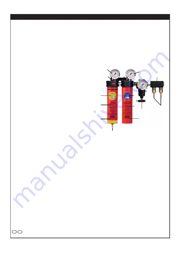
1 Pressure regulation T handle
2 Diaphragm and pressure regulation valve (not illustrated)
3 Gauge, stage A outlet pressure
4 Air inlet fitting G 1/2 inside thread
5 Filter housing tube, stage A
6 Integral automatic condensate discharger
7 Condensate drain hose
8 Filter housing tube, stage B
9 Coupling and hose nipple
10 Mounting angle
11 Gauge, stage B outlet pressure
12 Label filter exchange „sintered filter“ - yellow -
13 Label filter exchange „fine filter“ - blue -
Stage A (Sintered filter)
Stage B (fine filter)
Regulating valve (C), Outlet manifold (D)
When filter is installed, the label on tube (no. 5 and 8) must be visib-
le from the front. (The arrow on the filter body indicates the flow direction.
1. System operation
The SATA filter 200 modular filter line may be used for qurifiying compressed air. They separate the solid, liquid, and
partially gaseous components from air flowing through the unit. The protect the spray equipment and ensure perfect
refinish results in addition to providing clean air for worker health protection.
1.1. Filter stage (A):
The sintered filter, filtering stage 1, separates particles larger than 5
μ
m as well as condensed water and oil. An additio-
nal regulating valve (pos. 2), allows adjustment of outlet pressure. When condensation in the filter tube (no.5) reaches
a certain level, a built-in automatic condensate discharger (no. 6) opens, pressurizing the condensate and forces it out
through the drain hose (no. 7). A small non-drainable portion is left inside.
1.2. Filter stage (B):
A filter cartridge in stage B filter separates tiny particles according to the filtration capacity of the cartridge used.
Filter type 234, Filtration capacity 0,01
μ
m, 99,998 % separation
1.3 Regulating valve (C)
The regulating valve A allows fine adjustment of the outlet pressure; maintaining a constant pressure value with hardly
any fluctuations.
1.4. Outlet manifold (D):
The manifold is equipped with two couplings and two hose nipples for the hose DN9
Operating instructions SATA filter 200
IRL
GB
SATA filter 244
A
B
C
D
9
5
8
1
2
11
10
10
3
6
4
Æ
Art. No. 44404
12
13


