Sartorius PMA.Power Series Скачать руководство пользователя страница 16

16


Operating Instructions PMA 35001-X
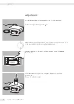
 Adjustment

Adjustment

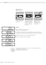
You can calibrate/adjust the scale by pressing the 

U

 key (Zero/Tare).  

Calibration weight: 10000 g; precision: +2%.

Always allow approximately 30 minutes for the scale to warm up after connecting it 
to AC power and before performing calibration/adjustment.

Press and hold the 

U

 key (Zero/Tare) for 2 seconds; “10000" is displayed. 

Release the key.

Center the calibration weight on the load plate. Adjustment is performed 
automatically. 
Remove the calibration weight.

Содержание PMA.Power Series

Страница 1: ...Operating Instructions Sartorius PMA Power Model PMA35001 X Electronic Paint mixing Scale for Use in Potentially Explosive Atmospheres 1000025334...

Страница 2: ...factor key for paint mixing applications 7 c key Clear and REC key for paint mixing applications 8 L ENTER key and MEM key for paint mixing applications Item Description 9 Mounting bracket for display...

Страница 3: ...nt Supplied 8 Installation 8 Operation 12 Applications 13 Calibration 16 Menu Setting 17 Error Messages 22 Care and Maintenance 23 Disposal 25 Interface Port 26 Specifications 27 Accessories 28 Docume...

Страница 4: ...manual from our website www sartorius com Warning Danger Symbols Warning danger symbols used in these instructions This symbol identifies hazards which have a high probability of resulting in death or...

Страница 5: ...Improper use or handling however can result in damage and or injury The manufacturer is not responsible for any damage caused by non compliance with warnings or safety instructions The requirements pe...

Страница 6: ...e checked for correct function and safety by a trained and qualified person at appropriate intervals e g checking the cable for damage Operating personnel must be trained to recognize faulty operating...

Страница 7: ...d personnel with the power disconnected The device is intended to be installed exclusively in locations that offer sufficient protection against the penetration of solid foreign bodies or water The sa...

Страница 8: ...age If you detect any damage proceed as directed in the Safety Inspections chapter page 23 Installation The color mixing scale is authorized for use in Zone 1 potentially explosive areas see documents...

Страница 9: ...acity and inductance values see appendix on EC Type Examination Certificate and the EMC behavior The system should only be operated for the first time when it is certain that the area is not potential...

Страница 10: ...ice professionals should be contacted Leveling the Weighing Platform Purpose To compensate for unevenness at the place of installation To ensure that the equipment is placed in a perfectly horizontal...

Страница 11: ...installation of devices in Zone 1 In order to connect the equipment to the power supply use a correctly installed wall outlet with a protective grounding conductor PE and a fuse of a maximum 16 A t Co...

Страница 12: ...lace an empty paint can on the load plate Press the U key Zero Tare 3 The display shows 0 0 g Pour the first component of your formula into the can and read off the weight when the stability symbol in...

Страница 13: ...or of up to 1 0 Note A flashing n arrow on the display indicates that the weight value displayed is not valid in legal metrology i e not legal for trade Example As you pour in the components of your f...

Страница 14: ...lues you entered and saved by pressing the L key MEM Press the S key to start the recalculation program C flashes on the display Press the S key to correct the value so that it matches the amount spec...

Страница 15: ...repeatedly to correct the value 200 0 g 10 Press the L key MEM COR 01 11 Add the required amount of the first component C1 appears on the display 1 7 g 12 Add until value reaches 0 0 g 0 0 g 13 Press...

Страница 16: ...precision 2 Always allow approximately 30 minutes for the scale to warm up after connecting it to AC power and before performing calibration adjustment Press and hold the U key Zero Tare for 2 second...

Страница 17: ...n level two Use the RS keys to select the desired menu item t Use the L key ENTER to select the next menu level level three t The third level menu is displayed Use the RS keys to select the desired me...

Страница 18: ...etting SETUP Press the L key ENTER SCALE Press the L key ENTER UNIT Use the RS keys to select e g SET GRAMS Press the L key ENTER KG o PT PD Use the RS keys toselect e g STANDARD SET Press the L key E...

Страница 19: ...key ENTER o indicates the active setting Press the c key Clear Activating the LOCK Function The LOCK function protects the scale from unauthorized use When this function is active the scale readout sh...

Страница 20: ...Keep a copy of your password in a safe place The LOCK function can be deactivated only with this password Level 1 Level 2 Level 3 Setting INPUT Use the RS keys to select INPUT PASSWORD Press the L key...

Страница 21: ...feature is password protected Level 1 Level 2 Level 3 Level 4 Setting SETUP Press the L key ENTER RESET Use the RS keys to select RESET Press the L key ENTER MENU Use the RS keys to select MENU Press...

Страница 22: ...hanges constantly The setup location is unstable Excessive vibration or draft Change the setup location Make the necessary adjustment via the scale operating menu see Menu Settings The weight readout...

Страница 23: ...for a relatively long time under unfavorable conditions In this case notify the Sartorius Service Center Maintenance and repair work may only be performed by authorized service technicians who have ac...

Страница 24: ...ntenance Do not apply any cleaning agents to ID labels or printed surfaces Corrosive Environment t Remove all traces of corrosive substances from the device on a regular basis Storage and Shipping Con...

Страница 25: ...o http www sartorius com 2 Select the Services tab 3 Then select Disposal Information 4 Addresses for the local Sartorius disposal contacts can be found in the PDF files available for download on this...

Страница 26: ...ve data Pin 3 TXD Transmit data Pin 4 DTR Data terminal ready Pin 5 GND Ground Pin 6 not used Pin 8 Clear to send CTS Make sure to observe the safety instructions t Remove the protective cover from th...

Страница 27: ...evice ID explosion protection II 2G Ex ia IIC T4 Gb DEKRA 12ATEX0180 X The terminal control panel is suitable for use in potentially explosive areas in accordance with Directive 94 9 EC Zone1 devices...

Страница 28: ...plosive area YPS02 XUR FM certified for the USA and Canada AC adapter for use outside of potentially explosive area YPS02 ZKR CSA certified for Canada AC adapter for use inside of potentially explosiv...

Страница 29: ...Operating Instructions PMA 35001 X 29 EC Declaration of Conformity...

Страница 30: ...30 Operating Instructions PMA 35001 X ECDeclaration of Conformity...

Страница 31: ...it against any further use 10 All metal parts must be electrically connected to the terminal for the equipotential bonding conductor PA The equipment operator must to connect a lead with a gauge of at...

Страница 32: ...32 Operating Instructions PMA 35001 X EC Verification...

Страница 33: ...Operating Instructions PMA 35001 X 33 EC Verification...

Страница 34: ...34 Operating Instructions PMA 35001 X EC Verification...

Страница 35: ...02 X Circuit Uo Io Po Co Lo V_1 12 6 V 133 mA 1 43 W 0 5 F 300 H V_2 12 6 V 133 mA 1 43 W 0 5 F 300 H V_3 8 6 V 186 mA 1 49 W 0 8 F 200 H V_4 12 6 V 150 mA 1 65 W 0 5 F 300 H Alternative connections S...

Страница 36: ...0 mH V_3 8 6 V 187 mA 1 51 W 391 nF 0 mH V_4 12 6 V 150 mA 1 68 W 223 nF 82 H 2 Power Supply YPSC01 X YPSC01 Z Circuit Uo Io Po Co Lo V_1 12 6 V 115 mA 1 45 W 0 5 F 350 H V_2 12 6 V 115 mA 1 45 W 0 5...

Страница 37: ...b IIC or YCO01 Y interface converter II 2 GD EEx ib IIC or II 3 2 GD EEx nR ib IIC T4 FC FCA IS X 3 scale weighing platform see remark 5 on page 3 Zone 1 Gas IIC T4 Hazardous Area Non Hazardous Area Y...

Страница 38: ...Co 13 5 F Ci 1 nF 8 4 F Lo 0 7 mH Li 1 6 H 0 7 mH Lo Ro 36 H 36 H Up to 7 additional CIXS3 or SIWS ISXS 3 Data cable Recommended Sartorius cable YCC485 X with approx 10 H ohm and 120pF m wire wire up...

Страница 39: ...6 V 8 0 V 25 2 V Io 207 mA Ii 1 5 A Po 330 mW Pi 2 5 W Co 13 5 F Ci 1 nF 8 4 F Lo 0 7 mH Li 1 6 H 0 7 mH Lo Ro 36 H 36 H RS422 data interface 2 COM1 Uo 5 2 V Ui 8 6 V Io 290 mA Ii 210 mA Po 496 mW Pi...

Страница 40: ...40 Operating Instructions PMA 35001 X Certificate of Compliance...

Страница 41: ...Operating Instructions PMA 35001 X 41 Certificate of Compliance...

Страница 42: ...42 Operating Instructions PMA 35001 X Certificate of Compliance...

Страница 43: ...Operating Instructions PMA 35001 X 43 Certificate of Compliance...

Страница 44: ...orms are used to facilitate legibility in these instructions and always simultaneously denote the other gender as well Copyright notice This instruction manual including all of its components is prote...

Отзывы: