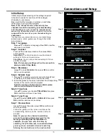
Introduction
6
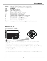
1 DIGITAL AUDIO OUT
2 USB 2.0/3.0
3 LAN
4 HDMI 1/2/3
(P.8)
(P.6)
(P.8)
5 AV IN
6 AUDIO OUT
7 ANTENNA
8 HEADPHONE
1
2
3
4
5
6
7
4
(P.7)
(P.8)
(P.12)
(P.7)
(P.7)
Basic Connection
Terminals
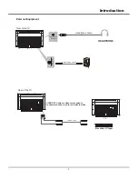
Power connection and aerial
ANTENNA cable
110 – 240 V ~
50/60 Hz
Note
TV
Aerial
Power Connection
Connect the TV’s power cable to a power outlet.
Do not place the RF cable under the TV.
7RREWDLQRSWLPXPTXDOLW\SLFWXUHDQGVRXQGDQDHULDOWKHFRUUHFWFDEOHȍFRD[LDODQGWKHFRUUHFWWHUPLQDWLQJ
plug are required.
If a communal aerial system is used, you may require the correct connection cable and plug between the wall aerial
socket and the TV.
Your Sanyo Service Centre or dealer may be able to assist you in obtaining the correct aerial system for
your particular area and the accessories required.
Any matters regarding aerial installation, upgrading of existing systems or accessories required, and the costs
incurred, are the responsibility of you, the Customer.
AC cord
2
8
LAN
HDMI 3
R
L
VIDEO
AV IN
DIGITAL AUDIO
OUT
5
V
0
5
A
HEADPHONE
HDMI 1
ANTENNA
5
V
0
9
A
HDMI 2
(SOUND OUT)
AUDIO OUT


