background image

– 20 –

4. USB STORAGE INFORMATION
    REGISTRATION

USB storage data is important for when the camera is con-
nected to a computer via a USB connection.
If there are any errors in the USB storage data, or if it has not
been saved, the USB specification conditions will not be sat-
isfied, so always check and save the USB storage data.

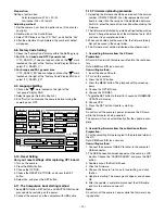
Adjustment method:

1. Connect the camera to a computer. (Refer to 3-5. Con-

necting the camera to the computer on the page 16.)

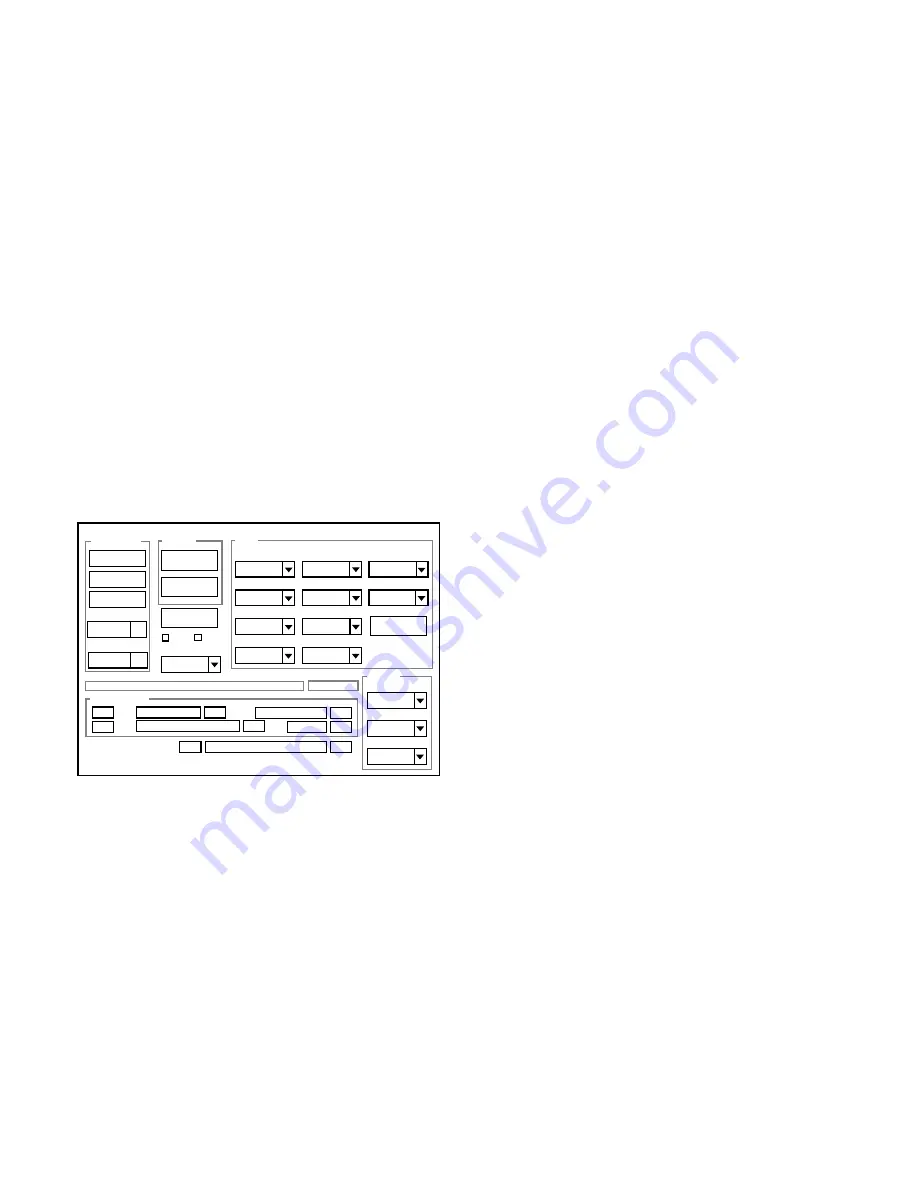
2. Double-click on the DscCalDi.exe.
3. Click on the Get button in the USB storage window and

check the USB storage data.
VID: SANYO
PID: E60
Serial:
Rev. : 1.00

4. Check the “Serial” in the above USB storage data. If the

displayed value is different from the serial number printed
on the base of the camera, enter the number on the base
of the camera. Then click the Set button.

5. Next, check VID, PID and Rev. entries in the USB storage

data. If any of them are different from the values in 3. above,
make the changes and then click the corresponding Set
button.

Firmware

Data

AWB

Focus

UV Matrix

RGB Odd

RGB Gain

Tint

RGB Even

VCOMDC

Phase

LCD

Calibration

Upload

PAF Cal.

LCD Type

H AFC

Test

VCOMPP(LOW)

VCOMPP(HI)

Cal Data

Cal Mode

OK

OK

EVF

USB storage

Get

Set

VID

Set

PID

Set

Serial

Set

Rev.

Set

Setting

Language

Video Mode

VCO

Factory Code

Backrush pulse :

Set

Get

Hall Cal.

Содержание VPC-E60

Страница 1: ...e wattage and voltage ratings shown CAUTION Danger of explosion if battery is incorrectly replaced Replace only with the same or equivalent type recommended by the manufacturer Discard used batteries according to the manufacturer s instructions NOTE 1 Parts order must contain model number part number and description 2 Substitute parts may be supplied as the service parts 3 N S P Not available as s...

Страница 2: ...alent and which lets you adjust the tip temperature up to 450 C 842 F It should also have as good temperature recovery characteris tics as possible Set the temperature to 350 C 662 F or less for chip compo nents to 380 C 716 F for lead wires and similar and to 420 C 788 F when installing and removing shield plates The tip of the soldering iron should have a C cut shape or a driver shape so that it...

Страница 3: ...7 8 9 11 5 6 10 16 V1 V3A V3B V1S V2 V3L V3R V4 Vertical register transfer clock Vertical register transfer clock Signal output 6 0 V 0 V 12 V Aprox 12 V Vertical register transfer clock VO V5L V5R V6 6 0 V 0 V 6 0 V 0 V GND Reset gate clock GND Circuit power DC 12 V GND 0 V 4 5 V 7 8 V ØRG 15 18 12 17 VDD DC Protection transister bias 6 0 V PT DC HL H1 Horizontal register transfer clock Substrate...

Страница 4: ...d from the SHP and SHD pulses and it is here that CDS correlated double sampling is carried out After passing through the CDS circuit the signal passes through the AGC amplifier VGA Variable Gain Amplifier It is A D converted internally into a 14 bit signal and is then input to ASIC IC101 The gain of the VGA amplifier is con trolled by pin A2 B3 and C4 serial signal which is output from ASIC IC101...

Страница 5: ...are made to obtain the optimum picture The data which has already been stored in the SDRAM is read by the CPU and color generation is carried out Each pixel is interpolated from the surrounding data as being either Ye Cy Mg or B primary color data to produce R G and B data At this time correction of the lens distortion which is a characteristic of wide angle lenses is carried out After AWB and γ p...

Страница 6: ...rol signal P ON are recontrolled to restore output 3 Analog System Power Output 12 V A 3 45 V A and 6 0 V A are output Feedback for the 12 V A is provided to the switching controller Pin 4 of IC501 so that PWM control can be carried out 4 Digital 3 25 V Power Output VDD3 is output Feedback for the VDD3 is provided to the swiching controller Pin 54 of IC501 so that PWM control can be carried out 5 ...

Страница 7: ...nsformer 1 5 Rectifier circuit The high voltage alternating current which is generated at the secondary side of T5401 is rectified to produce a high voltage direct current and is accumulated at electrolytic ca pacitor C5412 1 6 Voltage monitoring circuit This circuit is used to maintain the voltage accumulated at C5412 at a constance level After the charging voltage is divided and converted to a l...

Страница 8: ...I O O I O O O O I O O O O Serial clock output Backup battery charging control Camera charging control DC JACK detection LCD backlight brightness adjustment Touch sensor clock 66 kHz Barrier motor control Barrier motor control VDD Charge LED L lighting Self timer LED L lighting Battery temperature detection power control L ON Barrier motor PI power ON OFF AV JACK detection Hot line request from ASI...

Страница 9: ... ON OFF signal 44 LCD BL O Serial communication request signal 50 SREQ XCIN I Clock oscillation terminal for clock 32 768 kHz 52 53 NOT USED O BR PI E I Barrier motor PI input interruption RESET I Microprocessor reset input 45 TH TEMP I Internal temperature detection 46 TIME OUT I Camera charging completed detection 47 NOT USED O 48 BAT_TEMP I Battery temperature detection 51 SCAN IN 4 I Key matri...

Страница 10: ...d waits in standby for the battery to be attached again When a switch is operated the 8 bit microprocessor supplies power to the system as required The 8 bit microprocessor first sets the P ON signal at pin 40 to high and then turns on the DC DC converter After this high signals are output from pins 26 and 31 so that the ASIC is set to the active condition Once it is completed the ASIC returns to ...

Страница 11: ...r cover baria 5 Cover lens 6 FPC 7 Two screws 1 7 x 5 8 Assy motor barrier 9 Remove the solder speaker 10 Remove the solder microphone 11 Remove the solder 12 Three FPCs 13 Screw 1 7 x 3 14 Screw 1 7 x 3 5 15 Connector 16 CP1 board 17 Holder motor NOTE Discharge a strobe capacitor with the discharge jig VJ8 0188 for electric shock prevention When assembling tighten the screws order a b ...

Страница 12: ... REMOVAL OF LENS ASSEMBLY When assembling assemble order a b 1 Dec right 2 Microphone 3 Two screws 1 7 x 3 5 4 Cabinet back 5 Flexible PWB CP1 TB1 6 Shaft strap 7 Cover battery 8 Dec bottom 9 Dec left 10 Two screws 1 7 x 2 5 11 Lens assy ...

Страница 13: ...LCD TB1 BOARD AND CABINET BACK 1 Three screws 1 7 x 3 5 2 Spacer VF2 3 FPC 4 Remove the solder 5 LCD 6 Button set 7 TB1 board 8 Dec card access 9 Button menu 10 Dec button set 11 Button zoom 12 Cabinet back When assembling tighten the screws order a b c ...

Страница 14: ...tton power 8 Dec button power 9 Spring shutter 10 Button shutter When assembling tighten the screws order a b 11 Holder button shutter 12 Dec top LED 13 Remove the solder 14 Screw 1 7 x 2 5 15 Remove the solder 16 Assy lamp 17 Holder flash 18 Three screws 1 7 x 3 19 Stand 20 Two screws 1 7 x 3 5 21 Holder monitor 22 Two screws 1 7 x 3 screw lock with glue 23 Holder strap 24 Speaker 8 25 Holder bat...

Страница 15: ... 15 2 5 BOARD LOCATION TB1 board ST1 board TB2 board CP1 board ...

Страница 16: ... for PC 4 Pattern box color viewer Turn on the switch and wait for 30 minutes for aging to take place before using Color Pure It is used after adjusting the chroma meter VJ8 0192 adjust color temperature to 3100 20 K and luminosity to 900 20 cd m2 Be careful of handling the lump and its circumference are high temperature during use and after power off for a while 5 Computer screen during adjustmen...

Страница 17: ...he DscCalDi exe 4 Click the Focus and click the Yes 5 Lens adjustment value will appear on the screen 6 Click the OK Measuring Point ADJ Location Measuring Equipment ADJ Value CL501 Frequency counter VR501 499 5 1 kHz Camera Collimator VR501 CL501 COMPL PWB CP 1 636 089 9087 IC501 Oscillation Frequency Adjustment Lens Adjustment AWB Adjustment CCD White Point Defect Detect Adjustment CCD Black Poi...

Страница 18: ...AGC CHECK and MS values If AGC a1 a2 a3 a4 a5 CHECK wc0 wc1 wc2 and MS MS1 MS2 the adjustment values fulfill the conditions be low they are determined as within specifications Adjustment value determination 50 a1 310 100 a2 550 200 a3 750 300 a4 950 400 a5 1024 wc0 128 2 wc1 128 2 wc2 130 40 1550 MS1 3850 450 MS2 2750 Adjustment values other than the above are irrelevant 4 CCD White Point Defect D...

Страница 19: ...erwriting and click the Yes 5 Update is starting The message will appear and choose OK 6 After the update is complete disconnect the USB cable and turn the camera s power off Note Do not turn off the camera s power while the firmware is be ing updated Preparation Setting of pattern box Color temperature 3100 20 K Luminance 900 20 cd m2 Adjusting method 1 Set the camera 0 cm from the pattern box Do...

Страница 20: ... storage data VID SANYO PID E60 Serial Rev 1 00 4 Check the Serial in the above USB storage data If the displayed value is different from the serial number printed on the base of the camera enter the number on the base of the camera Then click the Set button 5 Next check VID PID and Rev entries in the USB storage data If any of them are different from the values in 3 above make the changes and the...

Страница 21: ...ECK X3001 IC301 55 OSCILLATION CHECK X3002 CHECK IC301 PUSH SHUTTER BUTTON IC301 17 20 SCAN IN 0 1 PULSE INPUT CHECK S3301 IC301 40 P ON CHECK IC301 SERIAL COMMUNICATION CHECK IC301 CP1 DMA BLOCK CHECK CP1 DMA BLOCK TAKING INOPERATIVE NO YES LOW LOW LOW NO NO NO YES HIGH HIGH HIGH YES YES YES HIGH OK NO LOW NG NO PICTURE CLK 48 MHz OSCILLATION CHECK X1102 IC301 63 64 ASIC_SO ASIC_SI CHECK CP1 INCO...

Страница 22: ... JNK 22 645 080 4144 MICROPHONE 23 636 089 6703 DEC RIGHT SX811 J 24 636 089 6697 DEC LEFT SX811 J 25 636 089 6833 HOLDER COVER BARIA SX811J 26 636 095 8395 COVER LENS SX816 J 27 645 079 2410 ASSY MOTOR BARRIER SX811 28 645 079 2397 LCD L4S00222P00 29 636 090 3784 SPACER BACK LIGHT2 SX811J 30 636 092 3911 SPACER BACK LIGHT SX811 J 31 636 089 9513 ASSY WIRE JW172 LCD SX811 32 636 089 9520 ASSY WIRE...

Страница 23: ...IS PARTS 1 Cabinet 1 SX816 U 2006 02 Ver 1 104 103 101 101 104 24 29 30 31 34 32 33 38 39 40 41 29 37 28 22 21 20 25 26 27 105 105 17 13 12 11 8 9 4 4 5 14 45 109 15 16 102 36 35 101 101 101 6 7 1 3 2 10 19 18 23 44 42 43 ...

Страница 24: ...9 HOLDER FLASH SX811 J 16 636 089 9100 COMPL PWB ST 1 17 636 090 3821 SPACER MAINCON A SX811 18 636 090 5962 SPACER MAINCON B SX811 19 636 092 7285 SPACER ST1 SX811 20 636 090 7317 SPACER SHUTTER SX811 J 21 636 089 6796 HLD PLATE SHUTTER SX811 J 22 636 095 8388 SPRING SHUTTER SX816 J 23 636 089 6536 BUTTON SHUTTER SX811 J 24 636 089 6802 HOLDER BUTTON SHUTTER 811 25 636 089 6680 DEC TOP LED SX811 ...

Страница 25: ...25 CABINET AND CHASSIS PARTS 2 Cabinet 2 SX811 J 2005 08 Ver 1 1 2 3 4 5 6 7 106 8 9 10 11 12 107 107 13 15 14 17 18 108 19 20 21 22 23 25 26 24 27 28 29 16 106 101 102 102 30 101 106 ...

Страница 26: ...01 405 182 8507 TR EMH16 Q9509 405 183 7707 TR EMH10 INTEGRATED CIRCUITS IC101 410 585 8306 IC KS755U2464CBP IC103 409 588 5405 IC EDS2532AABH 75 IC121 409 667 9607 IC K5V3256VTA D976 IC151 409 638 7601 IC BH76806FVM IC171 409 651 9804 IC LC15016A EV IC181 409 609 8606 IC BH6412KN E2 IC182 409 505 9400 IC TK11130CS IC301 410 595 4008 IC LC875924A 57D5 E OR 410 587 2609 IC LC87F5932A F57D5 E IC302 ...

Страница 27: ...U Z 4V C3003 403 322 1005 CERAMIC 0 1U Z 16V C3004 403 322 1005 CERAMIC 0 1U Z 16V C3005 403 338 0306 CERAMIC 0 1U K 10V C3007 403 381 8106 CERAMIC 1U K 6 3V C3008 403 276 2806 CERAMIC 18P J 50V C3009 403 276 1007 CERAMIC 0 01U K 16V C3010 403 338 0306 CERAMIC 0 1U K 10V C3011 403 276 1304 CERAMIC 1000P K 50V C3012 403 317 2307 CERAMIC 20P J 50V C3013 403 338 0306 CERAMIC 0 1U K 10V C3014 403 338 ...

Страница 28: ...K DC 1 16W R3012 401 225 1405 MT GLAZE 47K JA 1 16W R3013 401 225 3805 MT GLAZE 1 5K JA 1 16W R3014 401 225 1306 MT GLAZE 470 JA 1 16W R3015 401 224 9006 MT GLAZE 10K JA 1 16W R5001 401 224 9501 MT GLAZE 2 2K JA 1 16W R5005 401 226 2401 MT GLAZE 560 JA 1 16W R5006 401 224 9501 MT GLAZE 2 2K JA 1 16W R5007 401 226 1503 MT GLAZE 0 000 ZA 1 16W R5009 401 261 5900 MT FILM 330 DU 1 16W R5010 401 261 39...

Страница 29: ...5 3507 DIODE MA4S111 D3309 407 235 3507 DIODE MA4S111 D3310 407 248 1804 LED QSMN C186 D5402 407 247 4004 DIODE RR255M 400 D5403 408 057 2808 DIODE HAP180N140DTP D5404 407 205 5203 DIODE RB521S 30 D5407 407 162 8507 DIODE DAN222 OR 407 151 6507 DIODE MA132WK TRANSFORMERS T5401 645 067 1869 TRANS STEP UP T5402 645 069 2420 TRANS STEP UP CAPACITORS C3301 403 282 5105 CERAMIC 470P K 50V C3302 403 276...

Страница 30: ...5 076 0235 CORD POWER 1 5MK VPC E60EX ONLY OR 645 057 1503 CORD POWER 1 2MK VPC E60EX ONLY 5 645 080 1846 ADAPTOR AC DC 6 645 063 5816 BATTERY RECHARGE LI ION 7 645 086 0850 DISC CD ROM SSP 816 U Sanyo Software Pack PDF INSTRUCTION MANUAL English French Spanish German Dutch Italy Chinese traditional Chinese Simlihied Korean Russian 9053 636 095 7381 INSTRUCTION MANUAL CAMERA SOFTWARE Englisn 636 0...

Страница 31: ...Feb 06 SANYO Electric Co Ltd Osaka Japan Printed in Japan ...

Отзывы: