background image

Содержание VHR-690

Страница 1: ...arate volume Materials I Model No Reference No rpROD cTsAFE The components designated by a symbol in this schematic diagram designates components whose value are of special significance to product safety Should any component designated by a symbol need to be replaced use only the part designated in the parts List Do not deviate from the resistance wattage and voltage ratings shown NOTE 1 Parts ord...

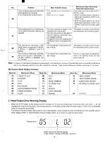
Страница 2: ...en the O button on the remote control unit is pressed during display and clearing the self diagnosis display and mechanism _ mode display r Display panel 171 i i 177 IJ _l l j 1 l_l II 1 I i Self Diagnosis number Mechanism mode number Reception channel display Tape counter Seconds display Self Diagnosis Contents No 00 01 02 03 04 05 Problem Main Possible Cause Mechanism Operations and State After ...

Страница 3: ... REVIEW 2 tact is faulty shifts to the INITIAL mode and the IDLER 3 STILL 4 BRAKE and power goes off to 5 STOP Note For details of mechanism operations corresponding to the mechanism positions of the self diagnosis numbers 08 and 09 above refer to the separate volume on the V95 1mechanism manual These manual reference numbers are shown in the cover Mechanism Mode Display Contents 00 01 02 03 04 05...

Страница 4: ...n out Envelope detec v tlonoutput IC301 Pln 25 or L blinking R3032 Markside Rental see Fig 2 l 1 ov k m han f Switching pulse cassette TP183 see Fig CH 1 CH 2 without tabs One video head is clogged 2 1 2 One video head has worn out Some rental cassettes may have extremely low video playback outputs even when both video heads are normal As the average output voltage of the two heads may be less tha...

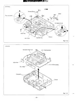
Страница 5: ...the two screws and two screws O of the performed with only the cabinet removed mechanism unit The two screws of the cassette tray can When replacing the bottom cover do not tighten the be removed easily by pushing the tray lock lever in the screws too much Excess tightness may damage arrow direction to remove the lock as shown in the enlarge the screws taps on the chassis view A and by pushing the...

Страница 6: ...M PK4HN E 2 Tray Lock Lever B Fig 1 1 2 M PK4HN E3 TM 2 PbV13 Assembly Chassis Fig 1 1 3 6 ...

Страница 7: ...rol facing up i L L M PK4HN E 4 CP 1 PWB Assembly Foil side Mechanism Main Unit 3 TM I PWB Cassette Cotipartment yu rM 2 PWB jr Fig 1 1 4 1 3 INSTALLATION OF THE FRONT PANEL When installing the front panel to the chassis after repaires and adjustments 1 Pressing down the door opener lever of the mechanism Note Opened cassette door position does not install the front main unit panel to the chassis ...

Страница 8: ...1 4 CIRCUIT BOARD LOCATIONS L PK4HN E E YA rv psembsymb y VH 3D6 i A l VHR 7 E TN 3 TN 5 P x 1 1A L W y c TM 2 P pw 8 ...

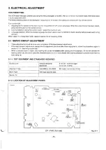
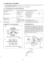
Страница 9: ... 3 have been finish ready to operate the all operating mode 2 1 SERVO CIRCUIT ADJUSTMENT These adjustments should be done upon completion of the tape transport adjustments If the tape transport adjustments except the tilt adjustment are done after these adjustments follow the procedures again in section 2 1 3 switching position adj When a cassette tape is loaded auto tracking will be set immediate...

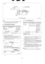
Страница 10: ...KING ADJ F Measuring Point Picture of monitor TV L pleasuring Equipment Color bar generator or broadcasting monitor I Adj Condition Self recording SP mode SLOW mode Blank tape Self recording LP mode SLOW mode Blank tape I Adj Location I Adj Value I 1 CHANNEL button I CHANNEL button I I 1 2 3 4 5 6 Set the tracking control to the center position by pressing CHANNEL buttons and simultaneously Play b...

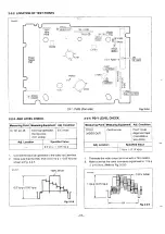
Страница 11: ...r bar signal waveform is described below Refer to Fig 2 2 1 I Adjust Relay Jig I VHJ 0067 12 wire flat cable for VP 1 PWB assembly ALIGNMENT TAPE COLOR BAR SIGNAL WPV TCS m I o 7vp p lvp p I Im n 1 1 100 White II f H Sync Si al Color bar signal waveform VHJ 0008 Fig 2 2 1 Color bar pattern VHJ 0008 on monitor TV Fig 2 2 2 ADJUSTMENT RELAY JIG Connect the flat cable end from the cylinder assembly t...

Страница 12: ...ng Equipment Adj Condition TP101 Oscilloscope PLAY mode VIDEO OUT Alignment tape VHJ 0008 or VHJ 0023 Adj Location Specified Value 1 Vp p 0 15 Vp p 1 Connect the color bar generator to the video input terminal 2 Make sure that the AGC level is 0 5 VP P t 0 05 VP P as 1 Terminate the video output terminal with a 75 resistor shown in Fig 2 2 5 WV AGC 1007 White 0 5 vp p o 05 Vp p h r t Fig 2 2 5 12 ...

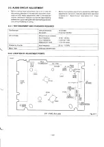
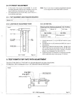
Страница 13: ...ween the supply side guide roller and loading guide post runs without fluttering or curling 2 3 1 TEST EQUIPMENT AND STANDARDS REQUIRED Oscilloscope Vertical sensitivity 10 mV DIV Bandwidth more than 30 MHz AC Voltmeter Effective value indication Input frequency 10 Hz 20kHz Input impedance more than 1 MQ Measurement level 1 mV full scale Frequency Counter Input frequency 20 HZ IO MHZ L Blank Tape ...

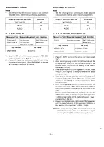
Страница 14: ...Press the INPUT button on the remote control and select AV After recording playing back for 10 to 20 seconds with the no signal input select Lch with the AUDIO button on the remote control and check the reading of the counter connected to TP233 If the carrier frequency of Lch is higher than 1 4 MHz rotate VR233 L FO slightly to the right towards the board component side Next switch to Rch and chec...

Страница 15: ...V Adj Location Adj Value VR RF AGC SIN is best point on the 3 in 1 tuner 1 1 2 3 4 Connect the monitor TV to the VHFIUHF antenna output terminal Connect the VHF or UHF antenna to the VHFIUHF antenna input terminal Receive the middle electrical field 70 dBp 90 dBp of the VHF or UHF channel and slowly turn the VR RF AGC from the point where snow noise is present to the point where it just disappears...

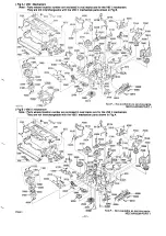
Страница 16: ...NLY SPACER MOTOR VHR 796E ONLY SPECIAL SCREW 2 3x6 SPECIAL SCREW 2 3X1O COMPL CASSETTEMEChlNISM STAND L FRAME UNDER SPRING LID OPENER LEVER R31LEASE SPRING TRAYLOCK GEAR LOCK GEAR PINION LEVER DOOROPENER HOLDER GEAR SPECIAL SCREW 2 6X6 PAD SCR S TPG BIN 4X12 LED LN59L PHOTODIODEPN263L NC PHOTODIODE0N2170 R PHOTOCOUPLESG 105F SPECIAL SCREW 2 6x8 A SPECIAL SCREW 2 6x5 5 ASSY REEL SUPPLY ASSY REEL TA...

Страница 17: ...95 II me f N S P Not availabie as service arts MECHANISM P RT 1 Note Parts whose location number are enclosed in oval marks are for the V95 II mechanism They are not interchangeable with the V95 I mechanism parts shown in Fig A m k 40000 J 801OA 0110 nninn 50210 00 701OA f Ufu 5ofIJB 1100 c w I i B 207 0 A w 20400 30400 39 A _ jj l 20410 Q zI r N S P Not avaiiable as service parts MECHANiSM PART 1...

Страница 18: ...GE CLUTCH 5030A 5030B 5030C OR 5040A 5040B 5040C OR 60100 60200 60300 60400 60500 60600 60610 60700 60800 60810 70500 6131522763 GEAR LOADS 6131520370 SPRING LOADS 6131518766 ASSY LEVER LOADS A 6131603691 ASSY LEVER LOADS B 6131522770 GEAR LOADT 6131520363 SPRING LOADT 6131518773 ASSY LEVER LOADT A 6131603707 ASSY LEVER LOADT B 6450034305 ASSY MOTOR LOADING 6131518599 COMPL GEAR WORM 6131519107 DA...

Страница 19: ...No CH N S P Not available as service parts K A wsi OR CH 16 CH 17 OR CH 19 OR CH 20 OR OR OR CH 21 OR OR OR CH 22 CH 23 OR OR OR cH 24 CH 25 CH 29 PAlws m DKXRIFW N o 6131603578 COMPL PWB AD 5 VHR 699 ONLY 6131665750 COMPLPWB TB l VHR 796E ONLY 6131605091 COVERBOTTOM VHR 796E ONLY 6131724723 COMPL COVERBOTTOM EXCEPTVHR 796E 6131709713 COMPL PWBTM 2 vHR 796E 0NL 6131681941 COMPL PWB TM 2 EXCEPTVHR ...

Страница 20: ...796E ONLY 4050144509 TR 2sc2412K R vHR 796E ONLY 4050144608 TR 2SC2412K S VHR 796E ONLY 4050640100 TR 2sA1561 Q vHR 796E ONLY 4050640209 TR 2SA1561 R VHR 796E ONLY 4051236708 TR 2SB1320A Q VHR 796E ONLY 4051236807 TR 2SB1320A R VHR 796E ONLY 4050026508 TR 2SA1179 M5 4050026706 TR 2sA1179 M6 4050020308 TR 2SA1037K R 4050020407 TR 2sA1037K s 4050026508 TR 25A1179 M5 vHR 796E ONLY 4050026706 TR 2sA11...

Страница 21: ...R 796E ONLY LA7910 EXCEPTVHR 796E L5631 UPC574J XLU2896K BU2896K L5431 UPC1093J PQ12RF11 EXCEPTVHR 796E LocAuDn D1101 OR D1102 OR D1103 OR D1104 OR D1105 OR D1106 OR D1201 OR D1202 OR D1221 OR D2301 OR D2302 OR 03001 OR D3102 OR D3105 OR D3106 OR D3108 OR D3109 OR D3116 OR D3117 OR D3502 OR D3505 D3506 DIODES 4070079904 DIODEGMAOI 4070124406 DIODE1SS133 4070079904 DIODEGMAO1 4070124406 DIODE1ss133...

Страница 22: ...O9 Clolo Cloll C1012 C1014 C1015 C1017 c1018 C102O C1021 c1023 c1024 c1025 c1026 c1027 C103O C1031 c1032 C1034 c1036 C1037 C1038 C1039 C104O c1042 C1043 C1044 C1045 c1046 C1049 cI052 C1053 C1054 C1055 c1056 C1057 C1058 C1059 c1061 c1067 Cllol C1102 C1103 C1104 C1107 c1108 C1109 Clllo C1201 C1202 C1211 C1401 C1402 C1403 C1404 C1405 C2101 C2102 C2104 c2106 c2301 c2302 c2303 c2304 c2305 c2306 C2307 c...

Страница 23: ...5v VHR 690 NEWZEALAND VHR 796E c3316 4031677002 ELECT 4 7U M 50V VHR 690 NEWZEALANO VHR 796E L C3317 4031213507 ELECT 4 7UM 50V EXCEPTVHR 796E WA uQN DzKRmLoL_ C3319 4031213408 ELECT 2 2U M 50V EXCEPTVHR 796E c3324 4030015003 CEPJIMIC 2200P K 16V EXCEPTVHR 796E C3351 4031219509 CERAMIC Odlu z 50V c3352 4030718102 CERAMIC 2200P K 50V EXCEPTVHR 796E C3401 4030149203 CERAMIC 180P J 50V c3402 40316862...

Страница 24: ...22K JA l 10 W EXCEPTVHR 796E 33K JA l 10W VHR 796E ONLY 22K JA l 10W 22K JA l 10W 15K JA l 10W vHR 690 NEWZEALAND OELY R2325 R2326 R2327 OR R2328 R2331 OR R2332 R2333 R2334 R2335 OR R2336 R2337 R2338 R2339 R2340 R2341 R2342 R2343 R2344 R2345 R2346 R2347 R2348 OR R2349 R2350 R2351 R2352 R2353 R2354 R2355 R2356 R2357 R2358 R2359 R2360 R2361 R2365 R2365 R2366 R2367 R2368 R2370 R2373 R2375 R2376 R2377...

Страница 25: ...5004 4010383801 MT GLAZE 330K JA l 10W R5005 4010375004 MT GLAZE 0 000 2A l 10W R5006 4010375608 MT GIAZE 10K JA l 10W R5007 4010376803 MT GKAZE 12K JA l 10W R5009 4010390502 MT GLAZE 82K JA l 10W R501O 4010193905 CARBON 390K JA l 4W R5011 4010193905 CARBON 390K JA l 4W R5020 4010622504 OXIDE MT 4 7K JA lW VHR 796E ONLY R5021 4010622504 OXIDE MT 4 7K JA lW VHR 796E ONLY R5022 4010622504 OXIDE MT 4...

Страница 26: ...A l 4W 330 JA l 10W 560 JA l 10W 22K JA l 10W 22K JA l 10W 390 J l 10W 390 Jh l 10W 1 2K JA l 10W 820 JA l 10W 330 JA l 10W IK JA l 10W 270 JA l 10W 1 5K JA l 10W 20K JA l 10W lK JA l 10W lK JA l 10W UxAzIol OR OR OR Q7101 OR Q7102 OR Q7103 OR Q7104 D7101 OR D7102 OR D7103 OR D7104 OR D7123 OR D7125 D7126 D7127 D7128 D7141 C7101 R7105 R7108 R7111 R7112 R7113 R7114 s7102 OR OR S7103 OR OR OR OR S71...

Страница 27: ...T VHR 796E ONLY L 2cAmN D8613 OR L8501 L8502 L8503 L8504 c8504 C8508 c8513 c8524 c8528 C8533 R8502 R8504 R8508 R8522 R8524 R8528 R8601 R8602 w w 6131665750 CWPL PWB TB 1 vHR 796E ONLY DIODES 4070701706 ZENERDIODEGZS15Y VHR 796E ONLY 4070997000 ZENERDIODEMTZJ15B VHR 796E ONLY INDUCTORS 6450087400 CORE BEAD VHR 796E ONLY 6450087400 CORE BEAD VHR 796E ONLY 6450087400 CORE BEAD VHR 796E ONLY 645008740...

Страница 28: ...30695601 CERAMIC O OIU K 50V 4031255606 ELECT 100U M 16V 4030695601 CERAMIC O OIU K 50V 4030695601 CERAMIC O OIU K 50V l Ams c6743 c6744 c6745 c6746 c6751 R6701 R6702 R6703 R6704 R6705 R6706 R6708 R6709 R671O R6712 R6714 R6715 R6716 R6717 R6718 R6741 R6742 R6743 R6744 R6745 R6746 R6747 R6748 4030730005 CERAMIC 4030730005 CERAMIC 4031079905 ELECT 4031079905 ELECT 4030095807 CERAMIC R31SISTORS 40103...

Страница 29: ...T GLAZE 4010375707 MT GLAZE 4010375707 MT GLAZE 4010375608 MT GIAZE 4010375608 MT GLAZE 4010383702 MT GLAZE 4010375202 MT GLAZE 4010375400 MT GLAZE O lu z 25V O lu 25V 220P J 50V 47UM 6 3V O lu z 25V 47U M 6 3v O lu PI 25V 0 039U K 50V 560P J 5Ov 0 047U K 50V 10U M 16v 470P J 50V 470P J 50V 470P J 50V 470P J 50V 10U M 16V 4700P K 50V 470P J 50V O lu z 25v O lu z 25v 1000P K 50V 680 JA l 10W lK JA ...

Страница 30: ...96E ONLY 6450031182 CABLE ANT PAL VHR 796E ONLY 6131326125 CABLE ANT VHR 796E ONLY 6450094569 CABLE ANT PAL vHR 796E ONLY 6130774415 CABLE ANT VHR 796E ONLY 6131325975 CORD EXCEPTVHR 796E 6130117359 CORD EXCEPTVHR 796E 6130966773 CABLE ANT EXCEPTVHR 796E 6131326132 CABLE ANT EXCEPTVHR 796E 6450069406 CABLE ANTPAL EXCEPTVHR 796E 6450027642 CORD POWER EXCEPTVHR 796E 6450122606 CORD POWER EXCEPTVHR 7...

Страница 31: ...Jun P96 l 950 NS Printed m apan Siqkmio SANYO Electric Co Ltd Osaka Japan ...

Страница 32: ...96E 28 CP 1 BOARD AD A AUDIO VHR 796L 29 CP 1 BOARD AD A AUDIO EXCEPT VHR 796E 32 IC301 SYSTEM CONTROL TIMER T JNING CONTROL MPU PIN FUNCTIONS TABLE 34 CP 1 BOARD SY A SYSTEM CONTROL TIMER TUNER IF CONNECTION EXCEPT VHR 796E 35 CP 1 BOARD SY A SYSTEM CONTROL TIMER VPS PDC TUNER IF CONNECTION VHR 796E 38 CP 1 BOARD SV A SERVO 4l sERvoclRculT waveforms 43 A71OI DISPLAY FLD GRID ANODE ASSIGNMENT DRAW...

Страница 33: ... w 7 El S N1 396L W E N1 E69 W C N1 I V S N1 9 3 lx 13im Z A UC 396L WA 1 669 tlHw r I ZC OOMI 1 WJOM I I l scOoM loL 1 ti3Nnl wn Ju E aso 03aIA oIanv j3W11 NO AS OAL13S H3MOd aow 4ml v a v av V AS V AS V hid d3 7VNINH31 I TOZN3 E xw J 3961 WO I HLl 1 av3H 03a IA 9NIEIIM11W 3A0 ...

Страница 34: ... D PG GND PG DRUM HEAD ALwAYS 3V Wi 3 GNDCMH 4 MOTOR D vS 5 D FG 6 0 crN4i7v A MC CAPSTAN MOTOR C FG i GND 2 GND MC 3 ALWAYS 13v FK A F R 5 C VS 6 SWD 5V 7 NC 8 TO C J A MC 5 ACE HEAD CN841 TO C jQJ A CTL CTL R P HEAD P R P HEAD R 4 ERASE 5 ERASE 6 T CP l AD A 30 CN 1 Pinl in4 1 FE HEAD 3 1 GND ERASE T CP l AO A 9 CN 01 P n51P n6 M1 154m m41 G H 17 I 18 I 19 I 20 I 21 I 22 I 23 I 3 ...

Страница 35: ... D I m I C_ I T A I 1 r 1 II u 2m D n c w u 7 ...

Страница 36: ... JJ 1 W d I 05010 APO I II I r I r b EM o u u o z m 3J UI c u D z i ...

Страница 37: ... fij j m T l 1 r 1 L x ...

Страница 38: ...VIDEO CIRCUIT WAVEFORMS WF V T WAVEFORM MODE I LEVEL PB o 3vp p PB 0 6Vp p REC 2 ovp p REC EE o 5vp p PB 0 6Vp p REC EE o 5vp p PB 0 6Vp p 16 I 17 I 18 I 19 I 20 21 _ I 22 I 23 I 18 ...

Страница 39: ... _ N I 1 I I I L t L t 1 I 3 y_ ...

Страница 40: ...ERM INAL VHR 796E TB 1 V3 1633141 uwa Td EURO AV1 a J J K J 0 I H G F E D c B A 1 I 2 1 3 I 4 I 5 I 6 I 7 I 8 21 2 CN851 AD IN AVt L 2 4 GM AD _ AD OUT L Al OUT R 5 e 6 4 _ _ __ EURO AV2 A I TO CP l AD A T II 1 J i ...

Страница 41: ...TB 1 P W B VHR 796E J 506 4V2 CH Cb1872 10 I 11 1 12 I 13 I 14 I 15 I 16 ...

Страница 42: ...cz 1 bl I c1 21 11 01 I 6 8 1 L 9 s P I c I z 1 1 I Iv I l a l I V dV 01 2WI 9 L I t V dV 01 v Z81 N3 J 130 AN3 9 H 33H 5 AM 4Mv MS At 3NAS 3 I 181N3 I 3 Hvw 0X91 ZA Q cM I I dWV 3kld03alA V dA CJUVOEI L dA ...

Страница 43: ... HEAD AMf IC291 LA7256 AZ 163WW I E4 VP 1 BOARD AP A AU D1OPRE AMP REC H AF REC I 5wD 5V r GND 7 I TO VP A I J AF COMMON AF OU 4GE REc SP P f SP MODE I TO VP A VP 1 P W B L 16 I 17 I 18 I 19 I 20 I 21 I 22 I 23 I 25 ...

Страница 44: ... IC291 LA7256 I I AF PB REC H AF REC I AF SW P SWD 5V GND A I TO VP A I J AF COMMON AF I vOLTAGE Pfc SP P U SF l NODE 1 TO VP A VP 1 P W B L HA w I AC4B 10B55900B mk IlLfI I EI VP 1 w UIC180 x w A a CMK P2X I 16 I 17 1 18 I 19 I 20 I 21 I 22 I 23 I 25 ...

Страница 45: ... I I cm w Hb 23 h d 1 I w i I l J WI P2559 mw L f 1 4 111 1 1 I I t I ...

Страница 46: ... Lf I I m 22 s 3 m _ r1 I 1 I 1 I I I I I I I 1 I I I II ...

Страница 47: ...AD 5 P W B VHR 699 VHR 796E I 18 1 19 I 20 I 21 I 22 I 23 I 24 ...

Страница 48: ... 4 1 Q l x I I I r X I I It L Hm 1 II I 1 I II I u w o 3J u D 9 c 0 E ii x 0 m a 3 1 R L 10 m m 6 L EWZ J I 6 ...

Страница 49: ...g pufw Input created by head drum PG I i O ay grm OUIPUIS FLDI e IC poweI supply fnput 5Vdc 23V input 107FLD drwe 3Oisfdaysegment OUIPUIS FLO Includes key scan output No T Name 1 0 I 53 SEG h o 54 SEG g o 57 SEG I 0 l f 56 SEG e 0 57 SEG d o 58 SEG C o 59 SEG b o 60 SEG a 0 1 61 REW LEO o n 62 f F LEO o H 63 PLAY LEO o H G4 DMSS LED o H k t 67 KEY IN 2 1 68 ITT OATA 69 POC MOOE 2 0 75 POC MO OE 1 ...

Страница 50: ... i I 11 r J1 I I 1 w 1 R3550 R3549 t k lM Ul j I I I I II I FIT J u I I I I ...

Страница 51: ...msec I R C Pin 3 m Pin 22 o 3vp p FSC INPUT 4 43 MHZ f CTL HEAD Pin 5 B v Pin 26 ROTARY CTL AMP OUT Bppvp p 20msec 20msec 40msec 2msec Pin 8 lJ j A v Pin 28 IJJJvvlomvp p D PG MM T C F i INPUT 7msec 0 66msec Pin 9 5 OV Pin 29 WJ30MVP P RF SW PULSE D FG INPUT 20msec 20msec 1 33msec Pin 10 BrJ 5 OV Pin 30 AF SW PULSE D PG INPUT lsomvp f 20msec 20msec 40msec Pin 11 mu Pin 28 COMPOSITE Lwov 4 2V ENVSW...

Страница 52: ... 5G 4G 3G 2G IG Xwtn PR L Q REC II AUTO EP b n n n n n c a a a a a a a a a d b b b b b b b b b e c c c c c c c c c f d 6 d d d d d d d 9 e e e e e e e e e h I f f f f f f f f I 9 9 9 9 9 9 I I m m m m m m m m m k B1l VPS cot 2 Col 1 Vcn R III PDC El DATE LP X G13 Com I 2 I 3 I 4 I 5 I 6 I 44 ...

Страница 53: ... 9b 3t LL 91 I 91 bl c1 I 21 11 I Oi 1 6 I e i I z zz 12 Oz 6 81 I iGQZ08 I VIVAV 1 0 CG8CCS I VIVAV1 l II I 1 mll3k E 3 3 1 k 9ic I 13 r L 396 L HHA S M d Z W1 Z wl I ...

Страница 54: ... I w I J 1 L 1 1 I 1111 j 1 ...

Страница 55: ...ii T o J2 c U3 4 n r 5 IZLN3 I d I II L H I M A 1 11111 1111 ll o n 0 1 z ...

Страница 56: ...T J d 1 ...

Страница 57: ...ii TN 5 P W B VHR 690 FOR NEW ZEALAND VHR 796E 16 I 17 I 18 I 19 I 20 I 21 I 22 I 23 I 2L i2 ...

Отзывы: