Scanning system :
PAL standard (625 TV lines, 25 frames/sec.)
Interlace :
PLL 2:1 interlace
Image device :
1/3 inch solid state image device CCD
Picture elements :
795 (Horizontal) x 596 (Vertical)
Effective picture elements :
752 (Horizontal) x 582 (Vertical)
Synchronizing system :
Internal sync, Line lock manually switchable
Resolution :
520 TV lines horizontally, 400 TV lines vertically
Video output level :
1.0 Vp-p/75
Ω
, composite
Video S/N ratio :
More than 48 dB
Minimum required illumination :
Approx. 0.3 lux with a F 1.2 lens (AGC, HI)
(incandescent lighting)
Approx. 0.6 lux with a F 1.2 lens (AGC, NORM)
Backlight compensation :
Manual MULT/CENT/OFF switching
(Active when using an auto-iris lens)
Iris function :
AI/EI selectable by switches (Electronic shutter)
Electronic iris range :
0.6 lux to 50,000 lux (F1.2, lens)
Electric shutter :
7 speeds, selectable by switches: (1/50, 1/120, 1/500,
1/1000, 1/2000, 1/4000, 1/10000 sec.)
Flange-back :
12.5 mm
±
0.5 mm
White balance :
ATW/Manual switching
Lens mount :
CS mount
AGC :
HI/NORM
Environmental conditions :
Temperature: -10
°
C ~ + 50
°
C
Humidity: less than 90 % (no condensation)
Power supply :
24 V AC, 50 Hz
Power consumption
: Approx. 2.8 W (with auto iris lens)
Approx. 2.1 W (without auto iris lens)
Weight :
Approx. 310 g (without lens)
Dimensions :
56 (W) mm x 45 (H) mm x 109 (D) mm
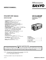
SERVICE MANUAL
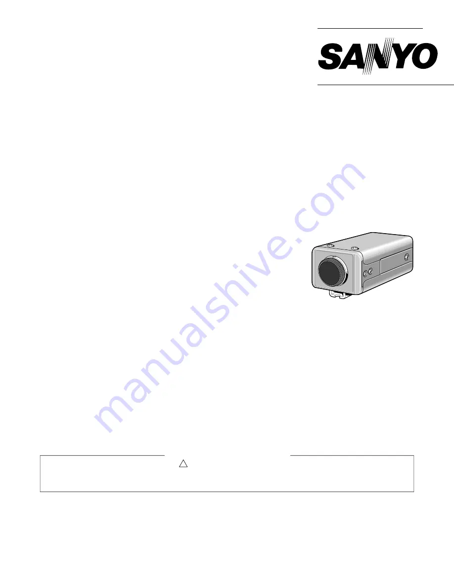
COLOUR CCD Camera
VCC-6594P
(Product Code : 117 108 04)
(South East Asia)
(Europe)
FILE NO.
REFERENCE No. SM5310325
L53H4/XE
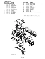
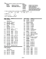
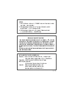
NOTE : 1. Parts order must contain model number, part number, and description.
2. Substitute parts may be supplied as the service parts.
3. N. S. P. : Not available as service parts.
Design and specification are subject to change without notice.
The components designated by a symbol ( ! ) in this schematic diagram designates components whose value are of
special significance to product safety. Should any component designated by a symbol need to be replaced, use only the
part designated in the Parts List. Do not deviate from the resistance, wattage, and voltage ratings shown.
PRODUCT SAFETY NOTICE
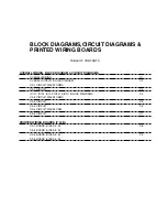
CONTENTS
1. DISASSEMBLY ....................................2
2. BOARD LOCATION ............................. 3
3. ADJUSTMENT ..................................... 4
4. PARTS LIST .........................................7
SCHEMATIC DIAGRAM
SPECIFICATIONS
Содержание VCC-6594P
Страница 12: ...Oct 01 SANYO Electric Co Ltd Osaka Japan ...
Страница 17: ...A B C D E F G H I J K 1 2 3 4 5 6 7 8 9 10 11 12 13 14 15 16 17 18 19 A B C D E F G H I J K C3 CA 1 CIRCUIT ...
Страница 19: ...A B C D E F G H I J K 1 2 3 4 5 6 7 8 9 10 11 12 13 14 15 16 17 18 19 A B C D E F G H I J K C5 CA 2 CIRCUIT ...
Страница 21: ...A B C D E F G H I J K 1 2 3 4 5 6 7 8 9 10 11 12 13 14 15 16 17 18 19 A B C D E F G H I J K C7 CA 4 CIRCUIT ...

