
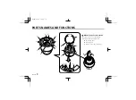

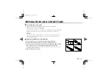


PARTS NAMES AND FUNCTIONS
1
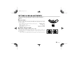
Camera unit fixing screws (4)
These screws are used to attach the camera unit to the base.
Tighten the four screws evenly when attaching the camera unit.
2
Screw openings for base installation
These openings are to attach the base to the ceiling or a wall
using the four supplied tapping screws.
3
CAMERA (VIDEO) OUT terminal screw
Video signal output terminal. Insert the center wire of the coaxial
cable into the CAMERA OUT terminal, then tighten the screw to
secure it.
4
GND (ground) terminal screw
Video signal ground terminal. Insert the shielding mesh of the
coaxial cable under the GND terminal plate, then tighten the
screw to secure it.
5
Cabling tab
When the cables cannot be run behind the ceiling, etc., remove
this tab to allow the coaxial cable to go through.
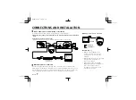
6
12 V DC input terminal
(12 V DC IN)
Connect DC connecting cord from the AC adaptor to the
12V DC
IN
terminal on the base. Then, plug the AC adaptor into an AC
outlet.
WARNING:
• This AC adaptor is specially conceived for this camera. Never use
another type of AC adaptor with this camera, and do not use this
AC adaptor to power other types of cameras.
• Not for use with toys.
• Never try to disassemble or modify the AC adaptor.
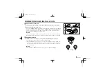
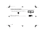
7
Lens cover
This cover will protect the lens from dust and damage. Turn the
cover in the direction of the arrow, shown on the illustration, to
remove it. To install the cover, align the tabs (A) with the
openings, then turn it in the opposite direction.
8
Secondary lens cover
9
Lens
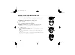
F
F
ocus ring
To set the focus, loosen the focus ring knob, then turn the ring
towards
∞
(infinity) or N (near) as necessary. When the focus is
set as desired, tighten the focus ring knob.
L53D2/XE GB 1998, 4, 14
4
English


