– 15 –
3-6. Adjust Specifications
[CP1 board (Side B)]
Note:
1. Voltage adjustment is necessary to repair in the CP1 board
and replace the parts.
Preparation:
1. Shorten the CL307 and CL310 (connection parts of power
switch wires).
2. Insert the CF card.
3. Connect the power, and turn on the LCD monitor.
1. 5.1 V (A) Voltage Adjustment
Adjustment method:
1. Adjust with VR502 to 5.10
±
0.05 V.
2. Back Focus Adjustment
Adjustment method:
1. Copy all the CCD calibration files to the CF card.
2. Click on Cmdfile.txt to activate the name field in the CF
card, and push the enter key to change the name to
“backfocus” using all lower case letters. Click the save but-
ton to save.
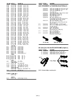
3. Take the lead of the pictured jig and solder it to the CP1
board, then connect the TV monitor. (Refer to page 14 be-
low figure.)
4. Set the CF card which is saved to the camera.
5. Slide the lens cover and put DC jack to the camera in order
to turn on the camera.
6. Set the siemens star chart 130 cm +5 /–0 cm so that it be-
comes center of the screen.
7. Set the macro lever (2) at normal position.
8. Turn the adjustment screw (1) until the siemens is exactly
in focus. Focusing is done by moving from far focal length
to near focal length (conterclockwise motion of the dial), so
start adjustment by moving to the far focus position if the
camera in not already at that position.
9. Set the siemens star chart 25 cm + 3/–0 cm from the cam-
era, check that the chart is out of focus this time.
10. Confirm that there are no operational problems in the com-
puter in taking still pictures in a set condition.
11. Pull the DC jack to turn off the camera after completing the
adjustment, and pull the CF card.
12. Remove the lead of the pictured jig. Confirm that there are
no operational problems in taking still pictures in a set
condition.
13. When this adjustment is carried out, it is necessary to per-
form the 3. CCD adjustment and 4. Strobe adjustment.
Perform the 4. Strobe adjustment after completing the
3. CCD adjustment.
3. CCD Adjustment
Adjustment method:
1. Copy all the CCD calibration files to the CF card.
2. Click on Cmdfile.txt to activate the name field in the CF
card, and push the enter key to change the name to “ccdcal”
using all lower case letters. Click the save button to save.
3. Set the CF card which is saved to the camera.
4. Set the color viewer 18 cm from the camera. Do not enter
any light at this time.
5. Slide the lens cover and put DC jack to the camera in order
to turn on the camera. Start the adjustment automatically.
When the adjustment is completed, the “OK” message will
appear on the LCD monitor. If an error occurs during the
process, the “EC***” message will be displayed, and you
must perform the adjustment again.
6. Pull the DC jack to turn off the camera after completing the
adjustment, and pull the CF card.
7. When this adjustment is carried out, it is necessary to per-
form the 4. Strobe adjustment.
Measuring Point
ADJ. Location
Measuring Equipment
ADJ. Value
CL528
Digital voltmeter
VR502
5.10
±
0.05 V
Camera
18 cm
All white pattern
Color viewer
CL528
VR502
(Side A)
CL415
CL413
CL414
CL400
CL411
CL307
CL310
Adjustment
screw (1)
Macro
lever (2)
Normal position

