17
Installation Site Selection
7-1. Indoor Unit
AVOID:
●
direct sunlight.
●
nearby heat sources that may affect performance of the
unit.
●
areas where leakage of flammable gas may be expected.
●
places where large amounts of oil mist exist.
DO:
●
select an appropriate position from which every corner of
the room can be uniformly cooled.
●
select a location that will hold the weight of the unit.
●
select a location where tubing and drain hose have the
shortest run to the outside.
●
allow room for operation and maintenance as well as
unrestricted air flow around the unit.
●
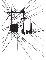
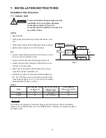
install the unit within the maximum elevation difference
(H1, H2, H3) above or below the outdoor unit and within
a total tubing length (L1+L2, L1+L2+L3) from the outdoor
unit as detailed in Table 1 and Fig. 1.
Table 1
INDOOR
UNIT (1)
INDOOR
UNIT (3)
INDOOR
UNIT (2)
Tubing length (L1)
L2
L3
Elevation
difference (H1)
H2
H3
OUTDOOR
UNIT
Fig. 1
WARNING
To prevent abnormal heat generation and the
possibility of fire, do not place obstacles,
enclosures and grilles in front of or
surrounding the air conditioner in a way that
may block air flow.
Max. Allowable Tubing
Limit of Total Tubing
Limit of Elevation
Model
Length per unit
Length (L1+L2) or
Difference (H1, H2, H3)
(m)
(L1+L2+L3) (m)
(m)
1923GJ
25
* 35 (L1+L2)
10
2433GJ
25
* 50 (L1+L2+L3)
10
This outdoor unit requires no refrigerant charge up to the maximum limit for total tubing
length of 35 m (CMRV1923GJ) or 50 m (CMRV2433GJ). Therefore, no refrigerant needs to
be added on-site.
NOTE
7. INSTALLATION INSTRUCTIONS

