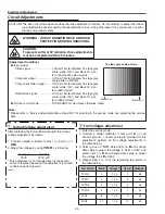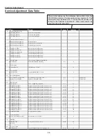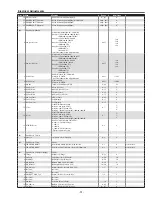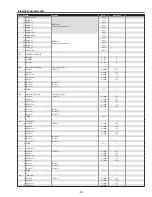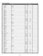
-25-
Electrical Adjustments
c
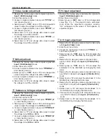
Video Center adjustment
1. Receive the 16-step gray scale computer signal with
Input 1 [RGB(Analog)]
mode.
2. Enter the service mode.
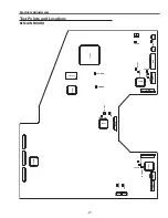
3. Connect a digital voltmeter to test point “
TPV1G
” (+)
and chassis ground (-).
4. Select group no. “
200
”, item no. “
0
” and change data
value to adjust the voltage to be
7.0
±0.05Vdc.
5. Connect a digital voltmeter to test point “
TPV1R
” (+)
and chassis ground (-).
6. Select item no. “
1
” and change data value to adjust
the voltage to be
7.0
±0.05Vdc.
7. Connect a digital voltmeter to test point “
TPV1B
” (+)
and chassis ground (-).
8. Select item no. “
2
” and change data value to adjust
the voltage to be
7.0
±0.05Vdc.
n
PC Input adjustment
1. Receive the 16-step gray scale computer signal with
Input 1 [RGB(Analog)]
mode.
2. Enter the service mode.
3. Select group no. “
680
”, item no. “
0
” and change data
value from 0 to 1. The projector starts self-adjust-
ment. When the adjustment completes correctry,
"OK" will appear on the screen. If "NG" appears, try
adjustment again.
v
NRS adjustment
1. Receive the 16-step gray scale computer signal with
Input 1 [RGB(Analog)]
mode.
2. Enter the service mode.
3. Connect a digital voltmeter to test point “
TPNRSA
” (+)
and chassis ground (-).
4. Select group no. “
200
”, item no. “
3
” and change data
value to adjust the voltage to be
2.5
±0.05Vdc.
5. Connect a digital voltmeter to test point “
TPNRSB
” (+)
and chassis ground (-).
6. Select item no. “
4
” and change data value to adjust
the voltage to be
7.5
±0.05Vdc.
b
Reference Voltages adjustment
1. Receive the 16-step gray scale computer signal with
Input 1 [RGB(Analog)]
mode.
2. Enter the service mode.
3. Connect a digital voltmeter to test point “
TPREF_G
”
(+) and chassis ground (-).
4. Select group no. “
200
”, item no. “
6
” and change data
value to adjust the voltage to be
9.38
±0.05Vdc.
5. Connect a digital voltmeter to test point “
TPREG_R
”
(+) and chassis ground (-).
6. Select item no. “
7
” and change data value to adjust
the voltage to be
9.38
±0.05Vdc.
7. Connect a digital voltmeter to test point “
TPREF_B
”
(+) and chassis ground (-).
8. Select item no. “
8
” and change data value to adjust
the voltage to be
9.38
±0.05Vdc.
m
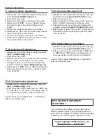
A/V Input adjustment
1. Receive the 16-step grey scale comosite video signal
with
Input 3 [Video]
mode.
2. Enter the service mode.
3. Connect an oscilloscope to test point “
TP35G
” (+)
and chassis ground (-).
4. Select group no. “
300
”, item no. “
2
” and adjust the
amplitude “a” to be
minimum
by changing the Data
value.
5. Receive the 16-step grey scale component video
signal (Y/Cb/Cr 480p) with
Input 3 [Y,Pb/Cb,Pr/Cr]
mode.
6. Select group no. “
300
”, item no. “
0
” and adjust the
amplitude “a” to be
minimum
by changing the Data
value.
7. Receive the 16-step grey scale component video sig-
nal (Y/Pb/Pr 1080i-60) with
Input 3 [Y,Pb/Cb,Pr/Cr]
mode.
8. Select item no. “
0
” and adjust the amplitude “a” to be
minimum
by changing the Data value.
9. Receive the 16-step grey scale component video sig-
nal (Y/Pb/Pr 720p-60) with
Input 3 [Y,Pb/Cb,Pr/Cr]
mode.
10. Select item no. “
0
” and adjust the amplitude “a” to
be
minimum
by changing the Data value.
11. Receive the 16-step grey scale component video sig-
nal (Y/Pb/Pr 720p-60) with
Input 3 [Y,Pb/Cb,Pr/Cr]
mode.
12. Select item no. “
0
” and adjust the amplitude “a” to
be
minimum
by changing the Data value.
(a)
White Level
Содержание PLV-80 Series
Страница 68: ... 68 IC Block Diagrams AD9882 AV A D IC8201 AD8183 AD8185 Selector IC3001 IC2002 ...
Страница 69: ... 69 IC Block Diagrams BA7078 Sync Separator IC3007 BH3540 Audo Amplifier IC1652 ...
Страница 70: ... 70 IC Block Diagrams L3E06110 S H IC501 IC531 IC561 FA5502 P F Control IC601 ...
Страница 71: ... 71 IC Block Diagrams L3E07090 Digital Gamma Correction IC401 LB1641 Motor Drive IC1602 IC1611 ...
Страница 72: ... 72 LB1645 Motor Drive IC1631 M62320 I O Expander IC5871 IC5872 IC Block Diagrams ...
Страница 73: ... 73 M62399 D A IC1501 IC7801 M62393 D A IC281 IC Block Diagrams ...
Страница 74: ... 74 PW388 Scan Converter System COntrol IC301 SP3232 RS 232C Driver IC3801 IC Block Diagrams ...
Страница 75: ... 75 STR Z2156A Power Switching Control IC651 TDA7056 Audio Output IC1631 IC1632 IC Block Diagrams ...
Страница 76: ... 76 IC Block Diagrams TE7780 I O Expander IC4801 ...
Страница 107: ...Key No Part No Description Key No Part No Description M4Y 8000 M4Y 80L00 107 Electrical Parts List ...
Страница 114: ... M4YA Nov 2005 BB 400 Printed in Japan SANYO Electric Co Ltd ...
Страница 118: ...Diagrams Drawings M4Y 8000 M4Y 80L00 ...

