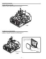
-18-
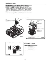
Note:
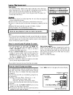
Do not replace the LCD
panel separately otherwise
it can not obtain proper
picture.
LCD Panel/Prism Ass’y Replacement
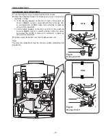
1
Remove the cabinet top and main board following to
“Mechanical Disassemblies”.
2
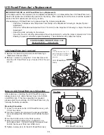
Remove 4 screws by using the 2.0 mm hex driver and
take the LCD Panel/Prism ass’y off upward from the opti-
cal unit.
LCD Panel/Prism
Ass’y
After replacing or installing the LCD Panel/Prism ass'y,
please make sure to obtain the best focus in both TELE
and WIDE zoom. If the focus adjustment is required,
please adjust the positioning of LCD Panel/Prism Ass’y by
following the below procedure.
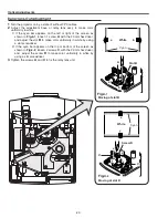
Mounting Procedure:
1
Loosen 4 screws
A
on the LCD Panel/Prism ass'y with
2.0 mm hex driver.
2
Turn the projector on and project the image with WIDE
zoom, and adjust the FOCUS control to obtain the best
focus.
3
Turn the ZOOM control to the TELE position.
4
Move the LCD Panel/Prism Ass’y backward or for-
ward (about 0mm ~ 0.8mm) to obtain the proper focus.
Confirm the focus at TELE and WIDE zoom.
5
Tighten 4 screws
A
to fix the LCD Panel/Prism ass'y.
Top View
A
A
A
A
LCD Panel/Prism Ass’y
IMPORTANT NOTICE on LCD Panel/Prism Ass'y Replacement
LCD panels used for this model can not be replaced separately. Do not disassemble the LCD Panel/Prism Ass’y.
These LCD panels are installed with precision at the factory. When replacing the LCD panel, should be replaced
whole of the LCD panels and prism ass’y at once.
After replacing LCD Panel/Prism ass’y, please check the following adjustments.
- Check the “Condenser Lens Adjustment” and “Relay Lens Adjustment” following to chapter “Optical
Adjustment”.
- Check the “White Balance Adjustment” and “Common Centre Adjustment” following to chapter “Electrical
Adjustment”.
- Check the white uniformity on the screen.
If you find the color shading, please adjust the white uniformity by using the proper computer and “Color
Shading Correction” software supplied separately. The software can be ordered as follows;
LCD Panel/Prism Ass’y removal
Note on LCD Panel/Prism Ass’y Mounting
COLOR SHADING CORRECTION Ver. 4.00
Service Parts No.
645 075 9611
Содержание PLV-80 Series
Страница 68: ... 68 IC Block Diagrams AD9882 AV A D IC8201 AD8183 AD8185 Selector IC3001 IC2002 ...
Страница 69: ... 69 IC Block Diagrams BA7078 Sync Separator IC3007 BH3540 Audo Amplifier IC1652 ...
Страница 70: ... 70 IC Block Diagrams L3E06110 S H IC501 IC531 IC561 FA5502 P F Control IC601 ...
Страница 71: ... 71 IC Block Diagrams L3E07090 Digital Gamma Correction IC401 LB1641 Motor Drive IC1602 IC1611 ...
Страница 72: ... 72 LB1645 Motor Drive IC1631 M62320 I O Expander IC5871 IC5872 IC Block Diagrams ...
Страница 73: ... 73 M62399 D A IC1501 IC7801 M62393 D A IC281 IC Block Diagrams ...
Страница 74: ... 74 PW388 Scan Converter System COntrol IC301 SP3232 RS 232C Driver IC3801 IC Block Diagrams ...
Страница 75: ... 75 STR Z2156A Power Switching Control IC651 TDA7056 Audio Output IC1631 IC1632 IC Block Diagrams ...
Страница 76: ... 76 IC Block Diagrams TE7780 I O Expander IC4801 ...
Страница 107: ...Key No Part No Description Key No Part No Description M4Y 8000 M4Y 80L00 107 Electrical Parts List ...
Страница 114: ... M4YA Nov 2005 BB 400 Printed in Japan SANYO Electric Co Ltd ...
Страница 118: ...Diagrams Drawings M4Y 8000 M4Y 80L00 ...

