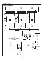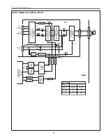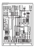
-23-
Electrical Adjustments
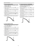
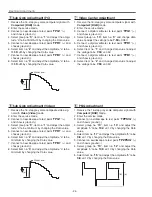
1. Receive the 16-step grey scale computer signal with
Computer2 [RGB]
mode.
2. Enter the service mode.
3. Connect an oscilloscope to test point “
TPG1
” (+) and
chassis ground (-).
4. Select group no. “
0
”, item no. “
0
” and change data
value to adjust the pedestal level and black level to be
the same level.
5. Connect an oscilloscope to test point “
TPR1
” (+) and
chassis ground (-).
6. Select item no. “
1
” and change data value to adjust the
pedestal level and black level to be the same level.
7. Connect an oscilloscope to test point “
TPB1
” (+) and
chassis ground (-).
8. Select item no. “
2
” and change data value to adjust the
pedestal level and black level to be the same level.
P
edestal Lebel
Blac
k Lebel
x
Clamp adjustment [PC]
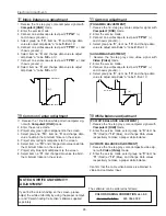
1. Receive the 16-step grey scale component signal
with
Computer2 [Component]
mode.
2. Enter the service mode.
3. Connect an oscilloscope to test point “
TPG1
” (+) and
chassis ground (-).
4. Select group no. “
0
”, item no. “
0
” and change data
value to adjust the pedestal level and black level to be
the same level.
5. Connect an oscilloscope to test point “
TPR1
” (+) and
chassis ground (-).
6. Select group no. “
0
”, item no. “
1
” and change data
value to adjust the pedestal level and black level to be
the same level.
7. Connect an oscilloscope to test point “
TPB1
” (+) and
chassis ground (-).
8. Select group no. “
0
”, item no. “
2
” and change data
value to adjust the pedestal level and black level to be
the same level.
P
edestal Lebel
Blac
k Lebel
v
Clamp adjustment [COMPONENT]
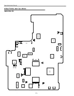
1. Receive the 16-step gray scale composite video sig-
nal with
Video [Video]
mode.
2. Enter the service mode.
3. Connect an oscilloscope to test point “
TPG1
” (+) and
chassis ground (-).
4. Select group no. “
0
”, item no. “
0
” and change data
value to adjust the pedestal level and black level to be
the same level.
5. Connect an oscilloscope to test point “
TPR1
” (+) and
chassis ground (-).
6. Select item no. “
1
” and change data value to adjust the
pedestal level and black level to be the same level.
7. Connect an oscilloscope to test point “
TPB1
” (+) and
chassis ground (-).
8. Select item no. “
2
” and change data value to adjust the
pedestal level and black level to be the same level.
P
edestal Lebel
Blac
k Lebel
c
Clamp adjustment [AV]
Содержание PLC-XU50
Страница 51: ... 51 IC Block Diagrams AD8075 Selector IC201 AN7513 Audio Output IC5601 ...
Страница 52: ... 52 BA7078 Sync Separator IC5341 IC Block Diagrams AN5870 RGB SYNC SW IC1201 IC5201 ...
Страница 53: ... 53 IC Block Diagrams BA7655 Audio Control IC5001 CXA7005R D A S H LCD Driver IC501 IC530 IC561 ...
Страница 54: ... 54 FA5502 P F Control IC621 IC Block Diagrams CXD3536 LCD Driver IC401 ...
Страница 55: ... 55 IC Block Diagrams M62392 M62393 D A IC6271 IC281 ML60851 USB Driver IC9801 ...
Страница 56: ... 56 STR Z2156 Power Switching Control IC631 TB1274 Video Decoder IC3101 IC Block Diagrams ...
Страница 57: ... 57 IC Block Diagrams TC90A69F Y C Separator IC2101 ...
Страница 82: ...MW3 XU5000 MT3 XU5500 Electrical Parts List 82 Key No Part No Description Key No Part No Description ...
Страница 84: ...MW3 XU5000 MT3 XU5500 84 S3 S3 S4 S3 S3 Mechanical Parts List S4 L4 Relay out L10 Integrator in Optical Parts ...
Страница 86: ...MW3 XU5000 MT3 XU5500 86 S5 S5 S5 L9 Projection Mechanical Parts List ...
Страница 87: ...MW3 XU5000 MT3 XU5500 87 Mechanical Parts List A D D E B C C L19 L13 L5 L8 L18 L11 L1 L3 L7 L12 L6 L14 ...
Страница 89: ...MW3 XU5000 MT3 XU5500 89 ...
Страница 90: ... MT3A Sep 2003 BB 400 Printed in Japan SANYO Electric Co Ltd ...

