-21-
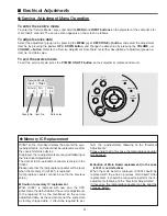
To enter the service mode
To enter the “Service Mode”, press and hold the
MENU
and
INPUT buttons
on the projector at the same time for
more than 3 seconds. The service menu appears on the screen as follows.
To adjust service data
Select the adjustment group no. by pressing the
MENU (+)
or
KEYSTONE (-) button
, and select the adjustment
item no. by pressing the pointer
UP
or
DOWN button
, and change the data value by pressing the
VOLUME –
or
button
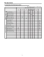
. Refer to the “Service Adjustment Data Table” for further description of adjustment group no.,
item no. and data value.
To exit the service mode
To exit the service mode, press the
POWER ON-OFF button
on the projector or remote control unit.
●
Service Adjustment Menu Operation
IC1801 on the main board stores the data for the serv-
ice adjustments, and should not be replaced except for
the case of defective device.
If replaced, the re-adjustments are required following to
the “Electrical Adjustments”.
The data of lamp replacement counter is stored in the
IC1801.
Please note that the lamp replace counter will be reset
when the memory IC (IC1801) is replaced.
(Lamp replace counter cannot be set to the previous
value.)
●
Caution to memory IC replacement
When IC1801 is replaced with new one, the CPU
writes down the default data of the service adjustments
to the replaced IC as the mentioned on the service
adjustment table. As these data are not the same data
as factory shipped data, it should be required to per-
form the re-adjustments following to the “Electrical
Adjustments”.
Please note that in this case the lamp replace counter
will be reset.
●
Caution of Main Board replacement (in the case
Ic1801 is not defective)
When the main board is replaced, IC1801 should be
replaced with the one on previous main board. After
replacement, it should be required to perform the re-
adjustments following to the “Electrical Adjustments”.
In this case, the lamp replace counter can be kept the
value as before.
●
Memory IC Replacement
ON
-
OFF
POWER
KEYSTONE
INPUT
WARNING
LAMP
REPLACE
MENU
V
O
L
U
M
E
–
V
O
L
U
M
E
+
SELECT
Service Mode
Input
Video
Group
No.
Data
0
0
32
Ver.
1
.00
Data value
Item No.
■
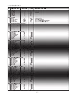
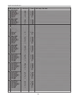
Electrical Adjustments
Group No.
Содержание PLC-XU50
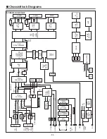
Страница 51: ... 51 IC Block Diagrams AD8075 Selector IC201 AN7513 Audio Output IC5601 ...
Страница 52: ... 52 BA7078 Sync Separator IC5341 IC Block Diagrams AN5870 RGB SYNC SW IC1201 IC5201 ...
Страница 53: ... 53 IC Block Diagrams BA7655 Audio Control IC5001 CXA7005R D A S H LCD Driver IC501 IC530 IC561 ...
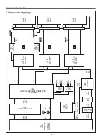
Страница 54: ... 54 FA5502 P F Control IC621 IC Block Diagrams CXD3536 LCD Driver IC401 ...
Страница 55: ... 55 IC Block Diagrams M62392 M62393 D A IC6271 IC281 ML60851 USB Driver IC9801 ...
Страница 56: ... 56 STR Z2156 Power Switching Control IC631 TB1274 Video Decoder IC3101 IC Block Diagrams ...
Страница 57: ... 57 IC Block Diagrams TC90A69F Y C Separator IC2101 ...
Страница 82: ...MW3 XU5000 MT3 XU5500 Electrical Parts List 82 Key No Part No Description Key No Part No Description ...
Страница 84: ...MW3 XU5000 MT3 XU5500 84 S3 S3 S4 S3 S3 Mechanical Parts List S4 L4 Relay out L10 Integrator in Optical Parts ...
Страница 86: ...MW3 XU5000 MT3 XU5500 86 S5 S5 S5 L9 Projection Mechanical Parts List ...
Страница 87: ...MW3 XU5000 MT3 XU5500 87 Mechanical Parts List A D D E B C C L19 L13 L5 L8 L18 L11 L1 L3 L7 L12 L6 L14 ...
Страница 89: ...MW3 XU5000 MT3 XU5500 89 ...
Страница 90: ... MT3A Sep 2003 BB 400 Printed in Japan SANYO Electric Co Ltd ...

