background image

STEP-2 Image Editing

21

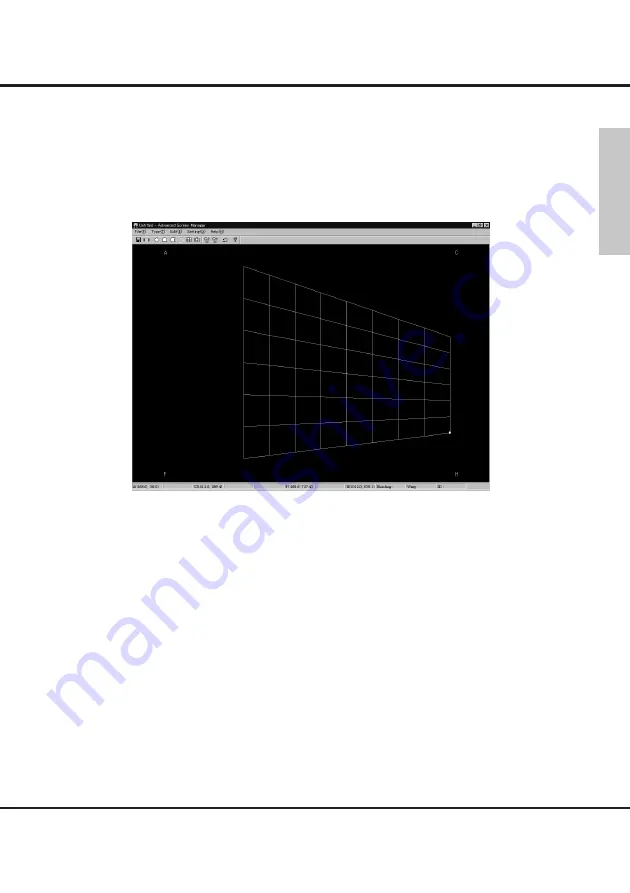
Keystone

This editing is for projecting diagonally on the flat screen.
Select "Keystone

y

" from either toolbar or Type(T)  in the menu.

The grid screen for keystone editing  appears.
Edit the image the same procedure as  editing on the spherical screen.

Click any of A, C, F, H points on the grid by a mouse, the points will appear on the
grid.
Edit the trapezoid with dragging the points by a mouse.
When you want to edit more details by gird unit. Select "Grid [transition]

i

" in the

menu, and edit by grid unit after basic editing. Refer to 

■ 

Grid [transition].

English

Содержание PLC-XF60

Страница 1: ...for any computer or system troubles data lost data corruption or malfunction of equipments caused by the software or mishandling We highly recommend to store the important data in the recording medium to another disc You may not copy the printed materials accompanying with the software The contents of this manual might be changed without notice The picture shape and screen display could be differe...

Страница 2: ...setting 15 Spherical 17 Horizontal curve 19 Vertical curve 20 Keystone 21 Grid New 22 Grid Transition 23 Blending 24 Confirmation of edited image 28 Sending 29 Center angle display 30 Screen Position Adjustment 30 Warp ON OFF 31 Blending ON OFF 31 Test pattern 32 2 Table of contents Table of contents Trademarks Microsoft Windows Windows 98SE Me Windows 2000 XP are registered trademarks and prod uc...

Страница 3: ...r curved screen with minimum distortion When using several projectors to project one image on a multiscreen the Blending function adjust image levels of overlapped parts These advanced functions enable you to use projected images more effectively at various events or visual presentation Projecting on a horizontally curved screen Projecting on a vertically curved screen Projecting on a spherical sc...

Страница 4: ...with Warp Blending Board at the time of purchase Compatible OS Main memory of the PC Recommended CPU of the PC Free hard disc of the PC HDD DIsplay setting of the PC Interface of the PC Windows 98SE Me 2000 XP RAM 256MByte or more Pentium3 500MHz or more 40MByte or more XGA 1024 x 768 or more SERIAL RS 232C Compatible signal Computer output Digital image Compatible with HDCP Signal format 640X480 ...

Страница 5: ...oard to the SERIAL terminal of the PC which is installed this software When operating several projec tors equipped with Warp Blending Board connect SERIAL PORT OUT terminal of Warp Blending board to the SERIAL PORT IN terminal of the next projector s Warp and Blending Board Connect the same way to another projector and link every projectors together English SERIAL To the SERIAL PORT IN of the next...

Страница 6: ...he signal input from SERI AL PORT IN When projecting Warp Blending image with several projectors con nect SERIAL PORT OUT to the next projector You can give the identified codes to each projector to control all of them individually Installation of the Advanced Screen Manager Mechanism and Function of the Warp Blending How to Start the Software 4 Installation of the Advanced Screen Manager Install ...

Страница 7: ...7 After starting up Advanced Screen Manager you will get the screen below With using this screen you can edit an image and project an edited image 7 Operation Screen of Advanced Screen Manager and Functions of Each Part Operation screen of Advanced Screen Manager English ...

Страница 8: ... file A Save the edited data after giving a name Menu Item The No is Toolbar icon No Spherical S e Horizontal curve H r Vertical curve Z t Keystone K y Grid New G u Function Page Edit to project on the spherical screen p17 Edit to project on the horizontally curved screen p19 Edit to project on the vertically curved screen p20 Edit the keystone distortion p21 Edit the grid p22 Grid transition I i ...

Страница 9: ... projector p13 Test pattern P Display the Test pattern p32 Optical axis setting L Set the Optical axis p14 View angle setting O Set the View angle p15 Center angle display T Display the Center angle p30 Screen position adjustment S Adjust the Screen position p30 Warp ON OFF W Select ON the edited image is displayed and select OFF the image without adjustment is displayed p31 Blending B Edit Blendi...

Страница 10: ... angle setting Set the view angle STEP 2 Image editing Select the type of editing suitable for the shape of the screen then edit the data Spherical correction Edit the image to project on a spherical screen You cannot edit images to project on a perfect spherical object Horizontal curve Edit the image to project on a horizontally curved screen Vertical curve Edit the image to project on a vertical...

Страница 11: ...oard stored there and remain even after turning off the projector CAUTION MAKE SURE TO SAVE THE DATA WHICH IS LOADED TO WARP BLENDING BOARD TO EDIT WITHOUT DATA SAVING YOU CANNOT CORRECT OR CHANGE THE EDITED DATA LATER AND YOU NEED TO CREATE THE DATA ALL OVER AGAIN YOU CANNOT READ OUT THE LOADED DATA TO WARP BLENDING BOARD LATER 11 Operation procedure Grid transition You can add partial editing to...

Страница 12: ...rojection screen Warp ON OFF Select ON or OFF of the curvature editing date which is sent to Warp Blending Board When selecting OFF the original date input into DVI terminal is projected without change Blending ON OFF Select ON or OFF of the blending editing which is sent to Warp Blending Board When selecting OFF the original date input into DVI terminal is projected without change Test pattern Pr...

Страница 13: ...ojector s ID No from the setting menu of the projector For details refer to the owner s manual of the projector 13 9 STEP 1 Setting of the Operation Configuration Resolution setting Select Resolution setting R from Setting O in the menu to display the Resolution setting dialog box Set the signal resolution which is input into DVI terminal from the input menu Adjust output resolution of the project...

Страница 14: ...he screen adjustable range is 0 1024 Y figure Set the vertical position on the screen adjustable range is 0 768 Upper left side is X 0 Y 0 position Setting example When the optical axis is at the center both horizontally and vertically X figure 1024 2 512 Y figure 768 2 384 When the optical axis is 30 from left sid and 70 from a upper side X figure 1024 x 0 3 307 Y figure 768 x 0 7 537 50 50 0 poi...

Страница 15: ...mall the distance between vertical lines of the right and left edge become shorter to show the irregular surface of the cylinder CAUTION WHEN THE PROJECTOR EQUIPPED WITH ZOOM FUNCTION SET THE VIEW ANGLE EACH TIME How to calculate the view angle When projecting with no warp state Select OFF in Warp ON OFF and calculating the view angle from dimentional measurement the formula is shown below Calcula...

Страница 16: ...roject on the horizontally curved screen Edit to project on the vertically curved screen 4 Keystone editing Edit to project diagonally on the flat screen 5 Grid New editing Edit to project irregular surface 6 Grid Transition editing Edit the details of any of 1 Spherical correction 2 Horizontal curve 3 Vertical curve 4 Keystone by cell unit 7 Blending Edit to project one screen with using several ...

Страница 17: ...rid Drag this point with a mouse and edit the grid shape You can also adjust with right click of a mouse and arrow key by 0 1 dot unit after selecting the adjustment points If the editing is not appropriate to project on a spherical screen or any of the cor ner points of the grid go over the size of the screen the square grid will disap pear At this stage you cannot edit each point nor send the da...

Страница 18: ...en When moving each of B D E G point equally to the edge of the screen Concaved surface Curve become steeper Convexed surface Curve become gentler When moving each of B D E G point to the center of the screen Concaved surface Curve become steeper Convexed surface Curve become gentler When you want to get the shape with four lines rounded toward inside on the screen select View angle setting and se...

Страница 19: ... the distance between vertical lines are not equal change the view angle figure from 10 to 60 1000 6000 in the View angle setting menu When the distance at the center is large and at both edges are small set the large figure CAUTION AFTER EDITING ANY OF A C F H POINTS THE PREVIOUS EDIT FOR THE SPHERICAL ROUNDNESS TO EACH OF B G POINT WILL BE RESET WHEN EDITING SPHERICAL ROUNDNESS YOU NEED TO EDIT ...

Страница 20: ...n the distance between horizontal lines are not equal change the view angle fig ure from 10 to 60 1000 6000 in the View angle setting menu When the distance at center is large and at both edges are small set the large figure CAUTION AFTER EDITING ANY OF A C F H POINTS THE PREVIOUS EDIT FOR THE SPHERICAL ROUNDNESS TO EACH OF D E POINT WILL BE RESET WHEN EDITING SPHERICAL ROUNDNESS YOU NEED TO EDIT ...

Страница 21: ...diting appears Edit the image the same procedure as editing on the spherical screen Click any of A C F H points on the grid by a mouse the points will appear on the grid Edit the trapezoid with dragging the points by a mouse When you want to edit more details by gird unit Select Grid transition i in the menu and edit by grid unit after basic editing Refer to Grid transition English ...

Страница 22: ...e projection screen Select Grid correctionu from Type T in the menu bar or toolbar icon The grid screen for Grid correction appears Edit each cell with dragging each point on the grid by a mouse Refer to See Spherical Horizontal curve Vertical curve Keystone for basic operation You cannot select Grid transition i for this operation ...

Страница 23: ... this function You can edit each cell individually by mouse drag Select this function then each adjustment item transit to this Grid correction transi tion After transition return to the previous item then each adjustment item will go back to the status before this adjustment Select Grid transition I to display the dialog box Select the editing type in the dia log Edit the same way as Grid correct...

Страница 24: ...g several projectors 1 First select the projectors to adjust Input projector s ID No in the STEP 1 Communication setting 2 Select Blending setting B from either toolbar or Type T in the menu then select 2Step or 16 Step depending on your editing The Blending screen will appear Editing differ between each editing step Edit along with the procedures of each step ...

Страница 25: ... Send the data to the projector and confirm the settings Repeat image editing with step1 3 for each projector and adjust the overlapped parts to get the natural image English 2 Step editing 1 Drag the lines or Xa Xb Ya Yb on the editing screen and adjust the overlapped widht of the images Each line show the screen position below Xa Left width of the screen Xb Right width of the screen Ya Top width...

Страница 26: ... set the figure with dialog by selecting Blending setting B in the Setting O menu 16 Step editing 1 Drag the lines or Xa Xb Ya Yb on the editing screen and adjust the overlapped width of the images Each line shows the following screen position Xa Left width of the screen Xb Right width of the screen Ya Top width of the screen Yb Bottom width of the screen 2 Adjust the offset level and layer linear...

Страница 27: ... screen 1 15 LEVEL2 Set the position level set by the POINT 1 16 POINT Set the point position of LEVEL 2 Set the position to locate which percent age from the screen edge Projector 2 Projector 1 Xb Xa Overlapped part 100 POINT LEVEL 1 Screen of projector 2 Screen of projector 1 LEVEL 2 Xb Xa English 3 Send the data to the projector and confirm the settings Repeat step1 3 for each projector and adj...

Страница 28: ...this function monitor out of the pc installed this software should be connected to DVI input terminal of Warp Blending Board with digital signal Select OFF in Warp ON OFF Press Alt and Z keys at the same time to display the edited grid image You can confirm how the edited image looks like Press Esc key to go back to the previous editing screen CAUTION VIEW ANGLE AND OPTICAL AXIS ARE NOT REFLECTED ...

Страница 29: ...ng Board of the projector Parts name of the dialog and functions qID No Display the ID No of the projector to send the data When you want to change the destination projector set the projector with ID No with STEP 1 Communication setting wStart Start sending the edited data to the projector eCancel Close the send dialog and go back to editing screen rConvert Display the conversion progress of binar...

Страница 30: ... STEP 1 Communication setting dialog Press Reset button to reset the position to standard location Center angle display Display the current center angle calculated by spherical correction or algorithm of hori zontal and vertical curve This dialog only show the current figure as a rough standard and you cannot change the figure ...

Страница 31: ...jected When selecting OFF the original image input into DVI terminal is projected without change English Warp ON OFF This function is to select ON OFF of Warp Before operation set the communication with STEP 1 Communication setting dialog When selecting ON the edited data which was sent to Warp Blending Board is projected When selecting OFF the original image input into DVI terminal is projected w...

Страница 32: ...een confirm the editing such as screen distortion linearity screen position Select Test pattern P in the Setting O menu to display the test pattern To cancel Test pattern press Esc key When using Test pattern function select OFF in Warp ON OFF W function To use this function monitor out of the pc installed this software should be connect ed to DVI input terminal of Warp Blending Board with digital...

Страница 33: ...33 ...

Страница 34: ......

Отзывы: