


20
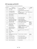
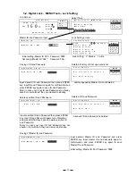
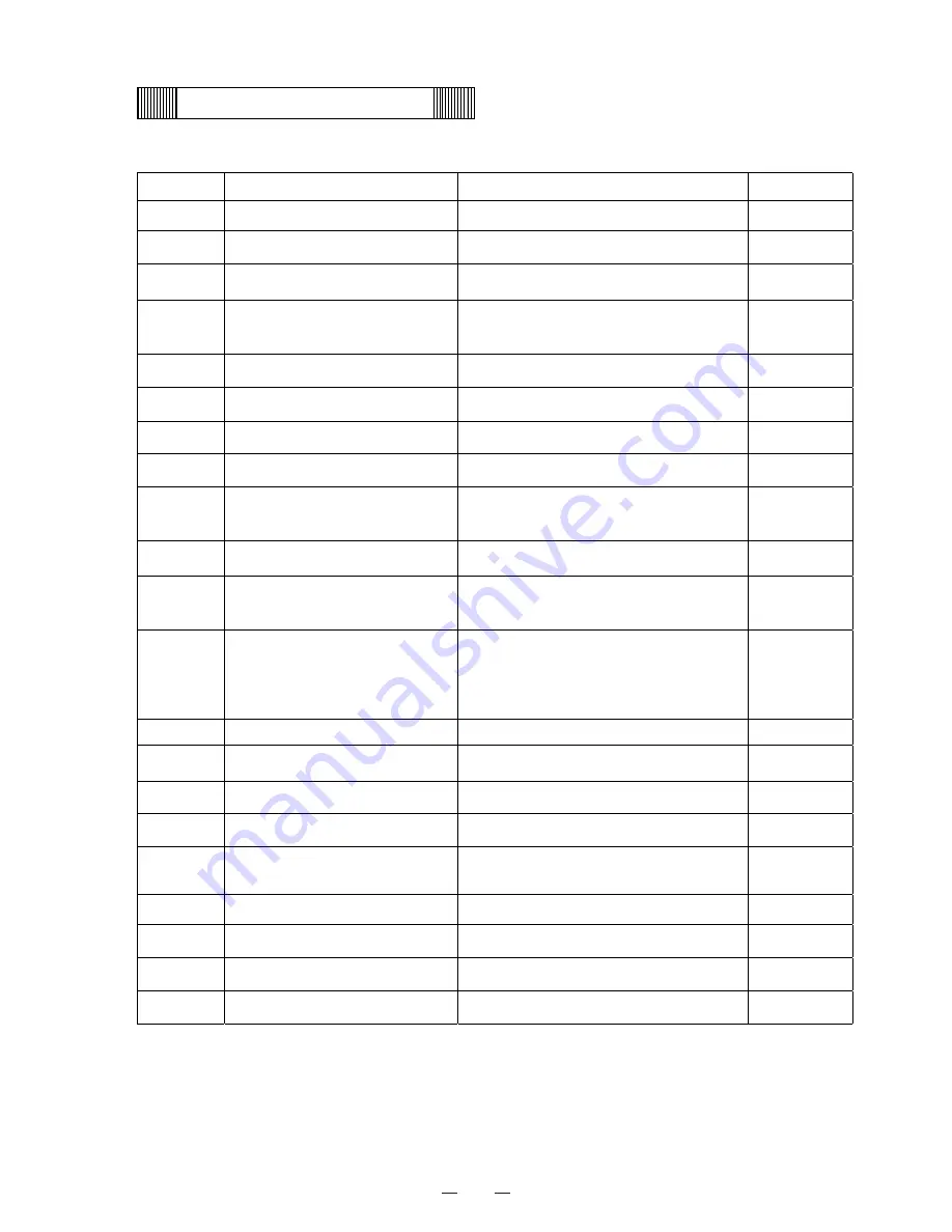
Connections on PCB
* Following are explanation of connections on the Main PCB.
Connector
Connects to
Usage
Voltage
CN1
Switching power supply
To supply the power to PCB.
#1: 12V
CN2
LCD module
To connect with LCD.
CN3
Control Board (CN5)
To connect with LCD contrast adjusting
knob.
CN4
#1-#2: Battery switch
#3-#4: Transformer(100V, 9V)
To supply the power to Main PCB
during power failure.
To detect abnormal low voltage.
#1-#2: 24V
CN5
Main PCB (CN3)
CN6
Main PCB (CN18)
CN7
MTR-480 (Option)
To connect with interface.
#1: 5V
CN8
#1-#2: Buzzer PCB
To connect with buzzer.
CN9
#1-#2: Temp. control relay H
#3-#4: Temp. control relay L
#5-#6: Heater relay
To control compressor H.
To control internal temperature.
To supply the power to cap. tube heater.
CN10
#3-#4: Door switch
To control digital lock (Option).
#1: 12V
#2: 5V
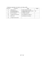
CN11
Remote alarm terminal
Remote switch
To output remote alarm
#1: COM
#2: N.C.
#3: N.O.
CN12
#1-#2: AT sensor
#3-#4: Filter sensor
#5-#6: Cascade sensor
#9-#10: Door switch
To detect ambient temperature.
To detect temperature at condenser
outlet pipe.
To detect temperature at cascade.
To control door switch.
CN13 Unused
CN14 LCD
module
To supply the power to back lamp for
LCD.
CN15
Main PCB (CN8)
CN16 Unused
CN17
#1-#2: Switching power supply
#3-#4: Lock
To supply the power to digital lock.
#1: 24V
#3: 24V
CN18
Control board (CN6)
To connect with each keys.
CN19
#3-#4: Back up PCB
To connect with back-up system.
CN20
#1-#3: Temp. sensor
To detect internal temperature.
CN21
#3-#4: Analog terminal
To output analog.
Содержание MDF-C2156VAN
Страница 9: ...6 Dimensions ...
Страница 11: ...8 Refrigeration circuits ...
Страница 12: ...9 Refrigeration circuit welding points 䌅䌁㩷 䌅䌂㩷 䌅䌃㩷 䌅䌄㩷 䌅䌆㩷 䌅䌇㩷 Pipe layout ...
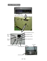
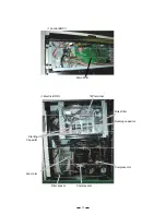
Страница 14: ...11 Components on PCB ...
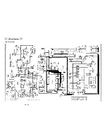
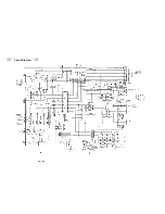
Страница 19: ...16 Wiring Diagram MDF C2156VAN ...
Страница 20: ...17 MDF C2156VANC ...
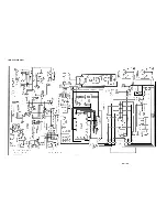
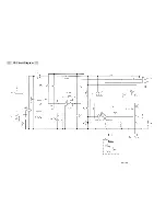
Страница 21: ...18 Circuit Diagram ...
Страница 22: ...19 CR Circuit Diagram ...