background image

Содержание MCD-Z8F (AU)

Страница 1: ...C 60 tape 80 12 000 Hz Normal Tape 2 channel 70 dB Undetectable 44 1 kHz 16 bits linear ch Semi conductor laser 790 nm Continuous wave max 0 6 mW PRODUCT CODE No 142 993 02 RADIO SECTION Tuning range Antenna GENERAL Power output UK Speaker Terminal impedance UK Power source Dimensions VVeight approx FM 88 108 MHz AM 525 1 710 kHz FM Telescopic rod AM Built in ferrite bar 4 0 W ch DC max 12cm x2 40...

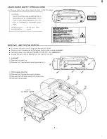
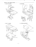
Страница 2: ...eliylk hikakso5Meesem A REMOVAL AND INSTALLATION Disconnect the power cord s plug from the electrical outlet All wiring should be returned to the original position after work is completed First have ready many the new FIXERS 614 129 4971 for replacement Arrange the lead wires so that they are not near the heat sink 1 CABINET 1 Remove the battery lid 2 Remove the 7 rear cabinet mounting screws 2 TO...

Страница 3: ... REMOVAL AND INSTALLATION 3 CASSETTE SECTION i 5 MAIN P W BOARD 0 POINT ADJUSTMENT J I l 2 ...

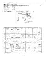
Страница 4: ...517 kHz Low end L2104 speaker erminals I 1750 kHz Max Hi h end VCT 4 2 3 4 Connect AM SG to Test Loop Connect AM SG to Test Loop Tuning coverage Tracking 2onnect VTVM to 600 kHz 600 kHz L2103 speaker terminals Max 1400 kHz 1400 kHz VCT 3 5 6 epeat adjustments 75 ohm unbal e VTVM Oscilloscope b FM ADJUSTh NT BAND SELECT SWITCH FM FM Dummy antenna i Adjusting Step Circuit 1 IF 2 Tuning 3 coverage 4 ...

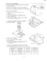
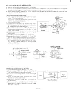
Страница 5: ... output are maximized k Press the the STOP button After completion of the adjustment use thread lock TB 1401B to secure the azimuth adjustment screw MOTOR REPLACEMENT AND SPEED ADJUSTMENT MOTOR MOTOR 1 Insert the test tape MTT IIIN etc 3000 Hz 2 Press the PLAY button 3 Use a flat tip screwdriver to turn the SVR located inside the rear of the motor to adjust SVR so that the frequency counter become...

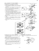
Страница 6: ... screws CM3 3 and remove the spindle motor CM3 5 4 Attach the special washer CM3 4 to the spindle motor I 5 Apply a small amount of a mixture of the Three Bond 2001 and 2015F bonding materials to the molor s shaft 6 Initial the turntable as shown in the figure Secure ihe iurn table by pressing gently Be sure to wipe away by using a price of cloth or similar material any bonding material coming out...

Страница 7: ...ckup rail CfV 2 through the new pick up CM9 The pickup P W Board pattern is shorted as shown in the figure so that the new pickup will not be susceptible to the effects of static Set the pattern to open after the pickup has been re placed SHORT CY3 CM8 4 Checking the action of the CD mechanism 5 Replacement of the sled motor 1 Disconnect the socket for the sled motor power supply 1 Remove the two ...

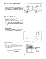
Страница 8: ...OSCILLOSCOPE SS5711 10 MHz and Dual Phenomenon I NOTE CD section of this unit can not need adjustment be cause CD P W Board checked at automatic check er 2 Confirm of general operation l Set the test disc 2 Press the PLAY button then confirm the disc rotating to clockwise direction 3 Press the FFWD or REW button then confirm the most in ner music or most outer music accessing at speedy 4 Press the...

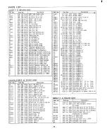
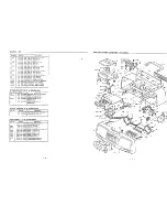
Страница 9: ...ABEL SAFETY LASER CLASS1 CORD POWER AC IN CORD POWER AC IN REMOCON MCD S660 BATTERY COVER REMOCON Description ASSY CABINET FRONT ASSY PANEL FRONT ASSY LIO CASSETTE ASSY CABINET REAR LIO CD HANDLE LID 8ATTERY KNOB ROTARY VOLUME KNOB ROTARY TREBLE BASS 8UTTON CD OPEN KNOB ROTARY TUNING KNOB SLIDE BAND BUTTON CD OPERATION KNOB SLIOE FUNCTION BUTTON SURROUND KNOB LEVER C MECHA BUTTON PANEL TOP CD ASSY...

Страница 10: ...KET 2P T0 OPEN CLOSE SW PLUG 4P T0 R P HEAD PLUG 4P T0 R P HEAD PLUG 3P T0 SPEAKER PLUG 3P T0 MECHANISM PLUG 3P T0 MECHANISM JACK HEADPHONE SOCKET OIP 4P SOCKET DIP 4P CORD 2P CONNECTOR ZENER DIODE MTZ8 2A DIODE 1SS133 DIODE GMAO1 Ref No D1507 or D4901 D4902 or HS401 ICIO1 ICI02 IC103 ICI04 IC105 IC401 IC 402 L1451 L4f701 L4801 L41301 L4902 PR 101 PR 102 QT 301 Q1401 Q A02 or or 501 or or Q 02502 ...

Страница 11: ... TREBLE 645 009 6815 VR ROTARY 50 KBx2 vOLUME UPEN CLOSE SWITCH P W BOARD ASSY 614 267 36o5 ASSY PWB OPEN CLOSE SWITCH 614 237 9752 SOCKET 2P TQ CO 4MP 614 035 4911 SOCKET 2P T0 CO AMP 645 004 9323 SWITCH LEVER 1P 2T OPEN CLOSE or 645 004 7787 SWITCH LEVER 1P 2T OPEN CLOSE BATERYTERMINALP W BOARD ASSY Ref No Part No Description 75 I 614 238 8778 lASsy pc6 LTATTERY TERMINAL I I 614 118 40361 TERMIN...

Страница 12: ...b9L0 110 9 9 lLLO 110 Sti9 88L0 110 st9 S6L0 10 sb9 1S0 802 I9 ON lied U3A31 NOllnE AVld 9 NIIJdS V 13A31 NOlln9 9NIMdS 9 M3A31 NOlLl19 9NItidS 1138 NIVW 1139 R3t13S 13 Y3VWZ UOLOW M3M3S f1383S U37303 80 LOW M3U S MO1OW 13X3VU9 d S N 9Z 0VOC5 93 UOIOW d S N A311nd WOLOW IIOLOW ASSV 133 HMA 14 ASSV lSnLIHl MJ SZOXO kXt Z N45 lV123dS U3HSVM JB 1139 H31n73 j d ASSV OX8 EXZI m d lV133dS M3HSVfl WV3 MV...

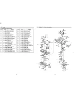
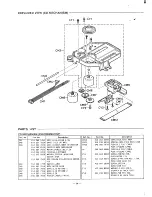
Страница 13: ...E DC 0 2W or TURNTABLE SPIIJDLE WASHER SPECIAL ADHESIVE CY1 ESCAPE STOP SCR PAN SW 2X5 SPINDLE MOTOR CY2 FIX SWITCH LIMIT CY3 ASSY MOTOR SLED GEAR SLED RETARD 1 CY5 GEAR SLED RETARD 2 GEAR SLED CY4 PICKUP LASER F P1OO 14 Part No 614 262 2599 614 238 6934 645 006 7976 645 009 5665 411 044 8004 411 152 4301 412 047 3904 411 088 6509 411 018 6401 Description GEAR RACK PICK RACK SPRING COMP PICK RACK ...

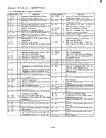
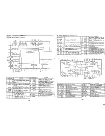
Страница 14: ...cessor 17 FD f Connection Pin for Constant of Focusing Phase 47 Vcoc o Output Pin for VCO Control Signal Compensation Consist of between FD and FA 48 Vco o Output Pin for VCO Signal 18 FA 1 Connection Pin for Constant of Focusing Phase 49 DEF o Output Pin for Defect Detection of Disc Compensation Consist of between FD and 50 CLK I Input Pin for Reference Clock Pulse Input FA 4 23 MHz of Digital Si...

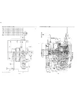
Страница 15: ... b 1411 149s 111 z I O3 s 1 1 111 1 s 6 1 8 11 a O BD w 0 o 1 I b I I w I ...

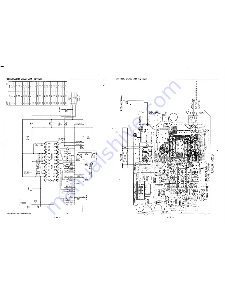
Страница 16: ... 1 8 5 0 0 6 5 4 7 7 6 5 4 7 8 6 5 47 9 0 0 10 11 12 74 2 1 13 1 0 1 0 14 10 i 0 15 75 2 5 16 6 5 2 2 17 2 7 2 2 18 0 7 07 19 1 5 12 20 65 4 7 21 65 4 7 22 65 4 7 23 65 4 7 24 6 5 4 7 FROM AMP CN41O o J 5210 52t01 2 L2103 I ROD ANTENNA z ml w I API IFI IER P W B ...

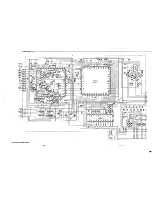
Страница 17: ...i _ 4i u m 4 4 m v s 311 I lll E J I II I I II IJ I J IL fl Id I I I I b 1 i m 2 I 0 N 1 ...

Страница 18: ... 7 w v w I I m r l r I 1 1 I I I r 1 1 1 1 I I I I 1 1 1 I 1 I 1 L I u L ...

Страница 19: ...w Il E z 4 c L 1 1 I I it 4 1 m 3 n I U N I I ...

Страница 20: ...6 3 dn 1 46 1 o P 93s Z ZHW cz aSlnd 130 JO indul LCISO 8 Iuau16as aal 101 Ieu61s dn VItll o 93s Cz uIJe3 puno g q uaw6es a l JOI eu6 s dn 1q611 o SSA L q 93s Zz SSA AV e waw6es a l Jo leu6 s d w6t7 9 v s 0 Mire pqs _ _ r u u ux t pals I o I 1s 6L Ieu6 s lJaAIJO V lq G3 I 10 FIJ6 S I I H3Lv7 viva dss pue dsa JOJ ej jai H3W IHL 0811S dSa 10J 4 JalUl I OUM L1 WUtl 0 eu6is LKW s c J o JO NI MS E I04U...

Отзывы: