3
Alignment instructions
1. Test equipment
VG-848 (YPbPr,VGA signal generator)
VG-849 (HDMI signal generator)
CA210 (white balancer)
2. Power test
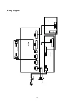
Connect data processing board, power board and IR board according the wiring diagram, connect
the power and press “standby” button to turn on the TV.
a) Test the pin voltage of X802, the data is shown in table1:
Table1 voltage data of X802
X802
Pin1
2
3
4
5, 6
7, 8
9
10
11
Voltage
8.55~9.45V
0
4.85~5.35V
0
11.4~12.6V 0 4.85~5.35V 0 >2.5
b) Test the pin voltage of XV01, the data is shown in table2:
Table2 voltage data of XV01
XV01
Pin1, 2
3, 4, 5
Voltage 23.8~25.2V
0
c) Test the pin voltage of X101, the data is shown in table3:
Table3 voltage data of X101
X101 Pin1
2
Voltage 31.4~32.6V
0
3. Alignment flow-chart
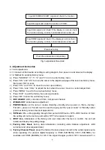
The alignment flow-chart is shown as fig-1
Check if DDC, HDCP KEY, FLASH are written
Connect to the center signal source and check each
function of TV (station leaking, analog control, etc.)
check the output of earphone and speaker.
Combined test for general assembly
White balance adjustment
Содержание LCD-47XR8DA
Страница 1: ...LCD 47XR8DA 1 682 344 41 CCIR DVB T SM0915046 ...
Страница 18: ...16 6 TDA1616 ...
Страница 19: ...17 ...
Страница 26: ......
Страница 27: ......
Страница 28: ......
Страница 29: ......
Страница 30: ......
Страница 31: ......
Страница 32: ......
Страница 33: ......
Страница 34: ......
Страница 35: ......
Страница 41: ...9247HE2710 Ver 1 0 ...


