- 21 -
IC BLOCK DIAGRAM & DESCRIPTION
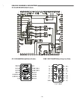
IC602 M34506M2-713(4bit Sigle chip, Microcomputer)
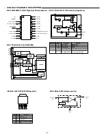
IC483 KA431AZTF(Voltage control)
Anode
(A)
Cathode
(K)
Reference
(R)
2.5Vref
+
-
IC850,851,852 PQ070XZ01Z(Regurater)
1
Description
DC INPUT
ON/OFF CONTROL
DC OUTPUT
OUTPUT VOLTAGE ADJUSTMENT
GND
1
2
3
4
5
Symbols
Vin
Vc
Vo
Vadj
2
3
4
5
Pin No.
1
2
3
4
5
6
7
8
9
10
20
19
18
17
16
15
14
13
12
11
P0
0
(I/O)
P0
1
(I/O)
P0
2
(I/O)
P0
3
(I/O)
P1
0
(I/O)
P1
1
(I/O)
P1
2
/CNTR(Timer output)
P1
3
/INT(Interrupt input)
D
0
(I/O)
D
1(I/O)
V
DD
V
SS
(GND)
X
IN
(Clock input)
X
OUT
(Clock output)
CNV
SS
(GND)
RESET
P2
1
/A
IN1
/(I/O)
P2
0
/A
IN0
/(I/O)
D
3
/K(I/O)
D
2
/C(I/O)
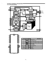
IC801 AT24C02N-1-SI-2.7(EEPROM)
8
VCC
4
GND
7
WP
3
A
2
2
A
1
1
A
0
6
SCL
5
SDA
DEVICE
ADDRESS
COMPARATOR
START
STOP
LOGIC
SERIAL
CONTROL
LOGIC
H.V. PUMP/TIMING
DATA RECOVERV
EEOROM
SERIAL MUX
D
OUT
/ACK
LOGIC
V DEC
DATA WORD
ADDR/COUNTER
R/W
D
IN
D
OUT
LOAD
INC
COMP
LOAD
FN
X DEC
IC490 STR-G6351LF1129(Switching Regulators)
DCP Comp.
UVI.O
+
-
+
-
+
-
+
-
+
-
4
REG
OSC
1
2
5
3
V
IN
D
S
OCP/FB/Tri
GND
Terminal No.
Symbols
Description
Functions
1
2
3
Drain terminal
Source terminal
Ground terminal
Overcurrent/Feedback/
Latch trigger terminal
MOSFET drain
MOSFET source
Ground
Input of overcurrent detection signal/
constant voltage control signal/
latch circuit operation signal
D
S
GND
OCP/F.B/Tri
5
4
Input of power supply for control circuit
V
IN
Power Supply terminal
Latch
Delay
Drive
REG
5 Q
K
Internal Blas
PWM Latch
Icanl
OVP
TSD
Tri


