background image

NETWORK SET SETTING

8

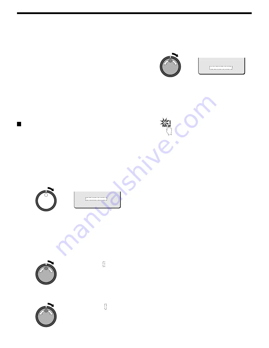
Turn the shuttle dial clockwise and use the jog dial and
shuttle dial to display the GATEWAY (example:
“ 192.168.0.1” ), and then turn the shuttle dial clockwise.

With the final shuttle dial operation, the cursor moves to the
PORT setting of “80”.

Note: When connecting this unit to a network, check the IP

ADDRESS, SUBNET MASK and GATEWAY settings with the
LAN Network Administrator.

9

Turn the shuttle dial clockwise, use the jog dial to enter the
PORT number (example: “ 90"), and then turn the shuttle dial
clockwise.

You can set any port number you wish within the range of 1 to
65535.

Note: If the port number is set to something other than the default

setting of “80”, type in the port number after the “

:

” in the IP

address.

PASSWORD SET setting

For network connection there are three access levels, each of which
has a password. Each password can consist of a combination of 4 to 8
alphanumeric symbols.

Note: The cursor cannot be moved to ID or PASSWORD (4-8).

Example: Set AB123456 as the ID1 password.

1

Use the jog dial to move the cursor to ID1, and then turn the
shuttle dial clockwise.

The initial digit 1 of the password entry flashes.

The characters that can be used in the password are: 0, 1 ... 9,
A, B ... Z

Note:

ID1: This level can only observe a live image through the network.

ID2: This level can observe a live image and play back and search

recorded images through the network.

ID3: This level allows all digital video recorder operations and

settings to be carried out.

2

Use the jog dial to display “ A” , and then turn the shuttle dial.

The second digit 1 flashes.

3

Use the jog dial to display “ B” , and then turn the shuttle dial.

The third digit 1 flashes.

4

Repeat this procedure to continue entering “ 123456” , and
then turn the shuttle dial clockwise.

The cursor moves to ID2.

5

As required, use the same procedure to set passwords for
ID2 and ID3, and then turn the shuttle dial clockwise.

The cursor moves to LAN CARD.

6

Press the EXIT/OSD button.

The display returns to the normal screen.

7

Computer operation

Refer to the separate Manual for Remote Operation by Network
Connection.

       PORT            : 00080
          ID           : PASSWORD (4-8)
          ID1          : 1111----
          ID2          : 2222----
          ID3          : 3333----

ID1          : A111----

ID1          : AB11----

       PORT            :  00080
          ID           :  PASSWORD (4-8)
          ID1          :  AB123456
          ID2          :  2222----
          ID3          :  3333----

EXIT/OSD

68

English

Содержание DSR-3000

Страница 1: ...nt d installer et d utiliser cet appareil veuillez lire ce manuel attentivement Assurez vous de le garder à portée de la main pour référence ultérieure Acerca de este manual Antes de instalar y usar este aparato lea detenidamente este manual Asegúrese de guardarlo a mano para futuras referencias Instruction Manual English GB Manuel d instructions Français F Manual de Instrucciones Español E ...

Страница 2: ... help For the customers in Canada This class B digital apparatus complies with Canadian ICES 003 CAUTION Danger of explosion if battery is incorrectly replaced Replace only with the same or equivalent type recommended by the manufacturer Discard used batteries according to the manufacture s instructions Model Number DSR 3000 Trade Name SANYO Responsible party SANYO FISHER COMPANY Address 21605 Plu...

Страница 3: ...NORMAL RECORDING AREA 19 SEARCHING FOR RECORDED IMAGES 24 SAVING COPYING RECORDED IMAGES 33 A Copying images to the hard disk archive area 34 B Copying images from archive area to a CompactFlash card 35 C Copying images from the archive area to a DDS DAT drive or CD R drive 37 MENU FLOW CHART AND MENU OPERATIONS 40 MENU flow 40 Basic menu screen operations 41 Operations while a sub menu screen is ...

Страница 4: ...r setting 57 Built in motion sensor settings 57 DISPLAY SET SETTING 59 DISPLAY SET setting 59 VIDEO LOSS SET setting 59 RS 232C RS 485 SET SETTING 60 RS 232C RS 485 SET setting 60 RS 232C Selection 60 RS 485 Selection 61 BUZZER SET SETTING 62 SECURITY LOCK SET SETTING 63 Operating privileges and security lock 63 A Administrator password setting 63 B User password setting 64 C Recording and playbac...

Страница 5: ...l video recorder Do not allow these ventilation holes to be covered when setting up the recorder Furthermore avoid using the digital video recorder in places with poor ventilation ACCESSORIES Power cord Fixer power cord tie Hard disk protection If any hard disk format errors are found when the power is turned on the whole hard disk is checked automatically If any further problems are found with th...

Страница 6: ... time and date and alarm status changes in the following order Displayed at top left Displayed at bottom left Displayed at top right Displayed at bottom right Off The indicator illuminates while information is displayed G SEARCH FRAME FIELD button and indicator During recording or when stopped When the button is pressed during recording or when the digital video recorder is stopped the indicator i...

Страница 7: ...input C Ground NC Spare NC Spare C Ground SW OUT Switching output C Ground Used for twisted pair cable connection O Alarm connector Pin Signal C Ground ALARM IN Alarm input ALARM RESET Alarm reset input ALARM OUT Alarm output NON REC OUT Non rec output C Ground CLOCK ADJUST IN Clock sync input See page 43 CLOCK ADJUST OUT Clock sync output See page 43 WARNING OUT HDD error warning output FULL HDD ...

Страница 8: ... O U T ALARM IN ALARM RESET NC C C OFF ALL RESET RS485 TERMINATE B A ON C RS485 REMOTE SUB OUT OUT DIGITAL VIDEO AUDIO S VIDEO SUB IN IN OUT OUT LOOP OUT LOOP OUT IN OUT IN MIC IN IN EJECT PC Card SLOT AUDIO IN Microphone input Video camera sold separately TV monitor sold separately VIDEO IN connector TV monitor sold separately S VIDEO IN connector Computer 32C S W O U T C C NC NC C C OFF ALL RESE...

Страница 9: ...d separately Alarm input When necessary Alarm output DIGITAL IN DIGITAL OUT Ground C STP Shielded Twisted Pair Cable straight type CAT 5 3 m or less AC IN RS232C A LA R M FU LL S W O U T W A R N IN G O U T FULL OUT IN ALARM OUT CLOCK ADJUST C C C NC C N O N R E C O U T ALARM IN ALARM RESET NC C C OFF ALL RESET RS485 TERMINATE B A ON C RS485 REMOTE SUB OUT OUT DIGITAL VIDEO AUDIO S VIDEO SUB IN IN ...

Страница 10: ... NC C N O N R E C O U T ALARM IN ALARM RESET NC C C OFF ALL RESET RS485 TERMINATE B A ON C RS485 REMOTE SUB OUT OUT DIGITAL VIDEO AUDIO S VIDEO SUB IN IN OUT OUT LOOP OUT LOOP OUT IN OUT IN MIC IN IN EJECT PC Card SLOT Digital video recorders with multiplexer function sold separately Digital video recorder sub 1 Digital video recorder sub 2 6 2 10 14 5 1 9 13 7 3 11 15 8 4 12 16 TV monitor sold se...

Страница 11: ...the normal recording area and the alarm recording area The size of the archive area can be set to a maximum of 10 GB 12 5 of total capacity when using an 80 GB hard disk 6 25 of total capacity when using an 160 GB hard disk by changing the size of the normal recording area or the alarm recording area Archive area C Normal recording area Normal recording area Normal recording area A Alarm recording...

Страница 12: ...H 0 17 6 3829H 2712H 2034H 1479H 1122H 0 13 8 5106H 3616H 2712H 1972H 1496H 0 10 10 6382H 4521H 3390H 2466H 1870H 0 05 20 12765H 9042H 6781H 4932H 3741H 0 03 40 25531H 18084H 13563H 9864H 7483H 0 02 60 38296H 27126H 20345H 14796H 11224H The tables below are recording time tables provided for reference if the total capacity of the hard disk has been increased to 160 GB Contact the place of purchase...

Страница 13: ... m m m m m m 3 75 0 27 m m m m m m m m m 3 33 0 30 m m m m m m m m m 3 00 0 33 m m m m m m m m m 2 73 0 37 m m m m m m m m m 2 31 0 43 m m m m m m m m 2 00 0 50 m m m m m m m m 1 67 0 60 m m m m m m m 1 43 0 70 m m m m m m m 1 25 0 80 m m m m m m m 1 11 0 90 m m m m m m m 1 00 1 m m m m m m m Default setting value recording cycle 0 1 second 10 FPS Recording time 1 minute The alarm duration menu se...

Страница 14: ...lay and alarm number display When an alarm setting is made using the ALARM REC MODE SET menu item The following display appears in the alarm display However the PRE display appears when pre alarm recording has been set When an alarm occurs the PRE is replaced by ALARM and the number of alarms also appears The alarm display shows the cumulative number of alarms If ALARM RECORDING is set ALARM appea...

Страница 15: ... EN Enhanced Recording method Field Recording speed 0 10 seconds 54H Note Playback is possible during recording When the PLAY STOP button is pressed during recording c appears in the operating display and images are played back from the point where recording began See page 20 Press and hold the REC STOP button for 3 seconds or more The a in the operating display disappears and recording stops Note...

Страница 16: ... is not set to ON or if the timer settings are not made correctly an alarm will sound when the TIMER button is pressed The TIMER indicator illuminates when the timer setting has been made correctly When the timer setting time is reached the TIMER indicator and the REC indicator illuminate and timer recording starts If you press the TIMER button during timer recording the TIMER indicator and the RE...

Страница 17: ... recording c appears in the operating display and images are played back from the point where recording began See page 20 Timer recording stops when the set end time is reached The TIMER indicator swithes off and the recording symbol a disappears from the operating display and recording stops Note Press the TIMER button to stop timer recording Timer recording then stops When the remaining area in ...

Страница 18: ...cording and timer recording stop when an alarm occurs during normal recording or timer recording Ending alarm recording Recording ends after the end of the alarm duration period default setting 1 sec The a and ALARM displays stop flashing and recording stops Note When the remaining area in the alarm recording area reaches 1 the ALARM FULL indicator on the front panel flashes If recording is contin...

Страница 19: ...cording method Field Recording speed 0 10 seconds 54H When an alarm is received pre alarm recording stops automatically and the alarm images are recorded The PRE disappears from the operating display ALARM flashes and the ALARM indicator flashes Note When the remaining area in the alarm recording area reaches 1 the ALARM FULL indicator on the front panel flashes If recording is continued under the...

Страница 20: ...ck See page 20 b Frame advance forward reverse See page 22 b Slow playback See page 20 Normal recording area Fast forward fast rewind playback See page 20 Locking speed for fast forward rewind playback See page 20 Releasing speed lock Normal playback When playing back recordings for the first time The recorded images will be played back from the beginning When playing back for the second or subseq...

Страница 21: ...ast forward playback starts If it is turned counterclockwise f appears in the operating display and rewind playback starts When you release the shuttle dial normal playback resumes PLAY STOP 1 10 26 01 11 02 50 EN 0 10SEC PLAY STOP 2 11 20 01 04 00 00 EN 0 10SEC 1 11 17 01 02 38 00 EN 0 10SEC 2 SHUTTLE HOLD Changing the playback speed Fast forward slow playback 1 Turn the jog dial clockwise Fast f...

Страница 22: ... Then turn the jog dial clockwise to move the zoom frame upward and turn it counterclockwise to move the zoom frame downward Move the zoom frame to the position to be enlarged Turn the shuttle dial The area inside the zoom frame is enlarged 2x Press the ZOOM button to cancel zooming The image zooming is canceled and normal playback continues Note The display cannot be enlarged even while monitorin...

Страница 23: ...ld Note If the jog dial is turned quickly the frame feed speed also increases STILL 1 11 17 01 02 38 00 EN 0 10SEC STILL 2 11 17 01 02 38 20 EN 0 10SEC 1 17 11 01 02 50 08 EN 0 10SEC During the following operations the picture may appear distorted or momentarily frozen This is normal and not a malfunction During the continuous playback from the normal and the alarm recording area the picture may b...

Страница 24: ...umbers channels can not be specified for playback When this operation is carried out only the specified channel is played back and so other channels are not displayed When a channel is selected the multiplexer title information and date information may not be fully displayed in some cases Switching between frame and field playback Press the SEARCH FRAME FIELD button while frame recording images ar...

Страница 25: ...H ALARM THUMBNAIL SEARCH TIME DATE SEARCH ARCHIVE AREA SEARCH MOTION DETECTION SEARCH MOVE JOG SELECT SHUTTLE ú ú ú ú ú ú ú ú ú LEVEL 6 EXIT MOTION DETECTION SEARCH SEARCH FROM NORMAL CHANNEL 4 START 10 28 01 08 00 END 10 28 01 20 00 MOTION SENSOR PREVIEW VIEW MOVE JOG SELECT SHUTTLE MOTION DETECTION SEARCH SEARCH FROM NORMAL CHANNEL 4 START 10 28 01 10 00 END 10 28 01 20 00 MOTION SENSOR PREVIEW ...

Страница 26: ...u can also use the shuttle dial or jog dial to carry out operations such as pausing and fast forward playback Alarm search starts playback from the image that was recorded at the instant the alarm occurred so if you are viewing pre alarm images use the shuttle operations to carry out rewind playback Alarm search 2 Press an ALARM skip button during playback If you press the û button playback skips ...

Страница 27: ...umbnails can be displayed When the jog dial is turned the previous or next alarm information screen appears To end this search mode press the SEARCH FRAME FIELD button Turn the shuttle dial clockwise The selected image appears in a single screen display and playback starts Note You can also use the shuttle dial or jog dial to carry out operations such as pausing and fast forward playback Only the ...

Страница 28: ...or as a single screen image Example To search for 8 pm on 26 October 2001 1 Turn the jog dial clockwise and select 10 2 Turn the shuttle dial clockwise and then use the jog dial to change 25 to 26 3 Turn the shuttle dial clockwise and select 01 4 Turn the shuttle dial clockwise and then use the jog dial to change 08 to 20 5 Turn the shuttle dial clockwise and select 00 Then turn the shuttle dial T...

Страница 29: ...and then turn the shuttle dial clockwise The preview image is displayed and played back in a single screen Note A single screen image can be displayed when date and time are entered and VIEW is selected even without displaying a preview You can also use the shuttle dial or jog dial to carry out operations such as pausing and fast forward playback 4 TIME DATE SEARCH RECORDING TOP 11 05 00 08 00 REC...

Страница 30: ...Turn the shuttle dial clockwise The selected image appears in a single screen display and playback starts Note A single screen image can be displayed when the cursor is moved to the image to be played back and the shuttle dial is turned clockwise even without displaying a preview You can also use the shuttle dial or jog dial to carry out operations such as pausing and fast forward playback SEARCH ...

Страница 31: ...huttle dial clockwise The ALARM display flashes Use the jog dial to select the recording area example NORMAL and then turn the shuttle dial clockwise The cursor moves to CHANNEL Note If the setting for MULTIPLEXER in the VIDEO INPUT SET menu is set to NO USE the cursor will move to START PREVIEW Examples of recording area selection ALARM Only images in the alarm recording area are searched NORMAL ...

Страница 32: ...e jog dial to set the END date and time example 8 00 pm on the current day for the motion sensor setting and then turn the shuttle dial clockwise The cursor moves to MOTION SENSOR Turn the shuttle dial clockwise The motion sensor setting screen appears Set the motion sensor to cover the area where you would like movement to be observed Move the cursor to EXIT and turn the shuttle dial clockwise Th...

Страница 33: ...hen turn the shuttle dial clockwise The display changes from the specified image to normal playback Note When using a multiplexer and the camera number has been specified as a channel when carrying out motion detector searches only images for the specified camera number will be played back For playback of all cameras the playback has first to be switched off and then switched on again Furthermore ...

Страница 34: ...n the RECORDING AREA SET menu to delete unneeded images Archive area Normal Normal recording area recording area Normal recording area Alarm Alarm recording recording area area Alarm recording area Hard disk Normal recording area Alarm recording area Normal recording area Alarm recording area Copying Copying CF card or microdrive CompactFlashCard Microdrive Normal recording area Alarm recording ar...

Страница 35: ...tle dial clockwise The cursor moves to PICTURES 6 Use the jog dial to select the SECONDS setting and then turn the shuttle dial clockwise PICTURES Specify the number of images to be copied SECONDES Specify the number of seconds of images to be copied MINUTES Specify the number of minutes of images to be copied up to 60 minutes The cursor moves to START 7 Turn the shuttle dial clockwise Copying of ...

Страница 36: ...r of seconds of images to be copied MINUTES Specify the number of minutes of images to be copied up to 60 minutes Note The limit to the number of images that can be copied is 40000 Copying ends when 40000 images have been copied When copying alarm recordings they can only be copied one at a time 6 Turn the shuttle dial clockwise The COPY indicator illuminates the COPY TO COMPACT FLASH screen appea...

Страница 37: ...ON Copying camera images to the archive recording area or to a CompactFlash card When the Digital Video Recorder is connected to a multiplexer including multiplexers from other manufacturers such as Robot DM and Sony you can copy images from a specified camera that have been recorded by the Digital Video Recorder to the archive area or to a CompactFlash card 1 Multiplexer operation Press the VCR b...

Страница 38: ...only CD RW discs cannot be used DDS Digital Data Strage DAT Digital Audio Tape Backing up All of the data in the archive area can be backed up on a DDS DAT drive 1 Press the COPY button during recording or when the digital video recorder is stopped The ARCHIVE SET screen appears 2 Use the jog dial to select BACK UP and then turn the shuttle dial clockwise ARCHIVING TO DDS DAT appears and copying t...

Страница 39: ...e images in the archive area the image data that has been read can be played back Deleting DDS DAT drive image data 1 Press the COPY button during recording or when the digital video recorder is stopped The ARCHIVE SET screen appears 2 Use the jog dial to select ERASE and then turn the shuttle dial clockwise The WARNING screen appears 3 Use the jog dial to change NO to YES and then turn the shuttl...

Страница 40: ...y from the normal recording area or alarm recording area to a CD R Depending on the duration of each event it may not be possible to copy all of the events specified The maximum amount of data that can be copied is 495 MB In the case of the EVENTS setting if you select the 60 setting copying will continue until the CD R becomes full 6Turn the shuttle dial clockwise The COPY indicator illuminates C...

Страница 41: ...D RECORDING CONDITIONS SET DIGITAL SERIES RECORDING OFF TOTAL NUMBER RECORDING NUMBER NORMAL RECORDING AREA OVERWRITE ON ALARM RECORDING AREA OVERWRITE ON REMAINING DISK WARNING TIMER SET WEEK START STOP REC CYCLE SET SUN 0 10SEC 54H OFF MON 0 10SEC 54H OFF TUE 0 10SEC 54H OFF WED 0 10SEC 54H OFF THU 0 10SEC 54H OFF FRI 0 10SEC 54H OFF SAT 0 10SEC 54H OFF DLY 0 10SEC 54H OFF ALARM REC MODE SET PIC...

Страница 42: ...e settings cannot be changed MENU MAIN MENU 1 1 LANGUAGE CLOCK SET 2 VIDEO INPUT SET 3 RECORDING AREA SET 4 RECORDING CONDITIONS SET 5 NORMAL REC MODE SET 6 TIMER SET 7 HOLIDAY SET 8 ALARM REC MODE SET TO MAIN MENU 2 MOVE LINES WITH JOG SELECT WITH SHUTTLE MAIN MENU 2 1 DISPLAY VIDEO LOSS SET 2 RS 232C RS 485 SET 3 BUZZER SET 4 SECURITY LOCK SET 5 NETWORK SET 6 HDD SET 7 POWER FAILURE USED TIME TO...

Страница 43: ... the shuttle dial clockwise The cursor moves to the 01 month setting and flashes 3 Use the same procedure to set the day 22 year 2002 hour 08 minutes 30 and seconds After the seconds have been set the cursor moves to the ADJUST TIME setting for EXT CLOCK SET and counting starts from zero seconds Note Time stops during clock setting LANGUAGE LANGUE IDIOMA ENGLISH CLOCK SET 01 01 2002 TUE 00 00 00 D...

Страница 44: ...d output terminal CLOCK ADJUST OUT at the rear of the digital video recorder CLOCK SET connection method Connect the C COMMON terminals of the first and second digital video recorder and then connect the CLOCK ADJUST OUT terminal of the first one to the CLOCK ADJUST IN terminal of the second one 2 Turn the jog dial to move the cursor to the ADJUST TIME setting and then turn the shuttle dial 01 fla...

Страница 45: ...mple and then turn the shuttle dial The cursor moves to MULTIPLEXER Note Select this if a Sanyo digital transport multiplexer MPX CD163 or CD93 has been connected digitally When making a multiplexer and a digital connection first connect the VIDEO OUT connector of this unit to the monitor and then set the input signal to DIGITAL 3 Press the EXIT OSD button The display returns to the normal screen ...

Страница 46: ...or some reason make sure that you make a backup copy of the images on some other medium such as a computer When the MIRRORING of the HDD SET setting has been set to ON the TOTAL CAPACITY display of RECORDING AREA SET shows a smaller value for the hard disk capacity Resetting each recording area Example Set the normal recording area to 50 and the alarm recording area to 49 1 Press the MENU button t...

Страница 47: ...der will flash When writing to the hard disk is complete you can use playback operations to check the recordings 2 Use the jog dial to move the cursor to the AREA FULL RESET setting for the NORMAL RECORDING AREA and then turn the shuttle dial clockwise NO flashes on the WARNING screen 3 Use the jog dial to change NO to YES and then turn the shuttle dial clockwise The NORMAL RECORDING AREA is set t...

Страница 48: ...ecorder which is used as the main unit should always have its connection number set to 1 Do not skip or overlap numbers when making the settings If NETWORK CONTROL in the NETWORK SET menu has been set to ON DIGITAL SERIES RECORDING cannot be selected Conversely if DIGITAL SERIES RECORDING has been set to ON NETWORK CONTROL cannot be set to ON The VIDEO INPUT SET for VIDEO INPUT of the second and s...

Страница 49: ...EXIT OSD button The display returns to the normal screen When the remaining disk space in each area reaches 5 it is displayed in the operating display section The FULL for normal recording area or ALARM FULL for alarm recording area indicator on the front of the digital video recorder flashes Relationship between RECORDING AREA SET and OVERWRITE If the normal recording area and alarm recording are...

Страница 50: ...kwise use the jog dial to set the recording speed example 0 13 and then turn the shuttle dial The cursor moves to PICTURE QUALITY Note The field and frame recording speeds vary depending on the PICTURE QUALITY setting Refer to the Recording speed table for details See page 11 7 Press the EXIT OSD button The display returns to the normal screen NORMAL REC MODE SET PICTURE QUALITY ENHANCED FRAME FIE...

Страница 51: ...icture quality frame field recording and audio recording settings for timer recording will be the settings used for recording in the normal recording area Timer reservations every day at the same time with the same image quality Example Timer recording every day from 8 30 a m to 6 30 p m at the same recording speed 1 Press the MENU button to select TIMER SET and then turn the shuttle dial clockwis...

Страница 52: ...be SUPER FINE Then recording speed the same as the speed previously set 9 Use the jog dial to change OFF to ON and then turn the shuttle dial clockwise The cursor moves to MON 10 Press the EXIT OSD button The display returns to the normal screen Note If you want to use different days times and recording speeds for timer recording select the respective WEEK column and make the required settings If ...

Страница 53: ... not need to be set appear with a symbol 6 Use the jog dial to change from TUE to WED and then turn the shuttle dial clockwise hours flashes in the STOP column 7 Use the jog dial to change from to 20 and then turn the shuttle dial clockwise minutes flashes in the STOP column 8 Use the jog dial to change from to 30 and then turn the shuttle dial clockwise 0 10 recording speed flashes in the REC CYC...

Страница 54: ...ine 1 3 Use the jog dial to change from to 11 and then turn the shuttle dial clockwise day flashes in the line 1 4 Use the jog dial to change from to 17 and then turn the shuttle dial clockwise The cursor moves to the line 2 5 Follow the same procedure to set other holiday dates 6 Press the EXIT OSD button The display returns to the normal screen HOLIDAY SET 1 11 2 12 3 13 4 14 5 15 6 16 7 17 8 18...

Страница 55: ...ORDED ALARM TRIGGER ALARM MOTION SENSOR Sub menus Main menu 1 Sets the image quality Sets the recording method frame or field Sets audio recording Sets alarm recording Sets the recording rate recording speed and the alarm time duration Sets pre alarm recording Sets the recording rate recording speed and the alarm time duration for pre alarm recording Sets the alarm trigger Sets the motion sensors ...

Страница 56: ...r This cannot be used for normal recording Note If alarm recording is set to a setting such as MODE1 PRE ALARM RECORDING setting will be enabled will change to OFF 7 Turn the shuttle dial clockwise use the jog dial to set the recording speed example 0 13 and then turn the shuttle dial DURATION of 1SEC flashes Note When the recording speed is selected the maximum number of recordings appears after ...

Страница 57: ...d with the pre alarm recording images If using the digital video recorder together with a multiplexer the switching signal from the multiplexer will be output in accordance with the digital video recorder s recording timing for normal recording if pre alarm recording and normal recording are being carried out at the same time Because of this if the recording cycle for pre alarm recording is shorte...

Страница 58: ...settings The monitor screen 8x10 can be displayed on the monitor screen so that detection of suspicious people alarms can be carried out more easily The default setting is for all motion sensors to be OFF so that they cannot detect the movement of objects Motion sensor screen Use the jog dial to move the cursor to MOTION SENSOR and then turn the shuttle dial clockwise The motion sensor screen appe...

Страница 59: ...nsitivity Note You can check the sensitivity in the setting screen When an alarm is detected the buzzer a beeping noise sounds If the sensitivity is too strong an alarm can be triggered by variations in light Make the setting that is appropriate for the area being monitored 4 Turn the shuttle dial clockwise twice This completes the motion sensor settings and the display is returned to the ALARM RE...

Страница 60: ...RECORDING in the ALARM REC MODE SET menu has been set to OFF ALARM COUNT and ALARM TYPE do not appear See page 54 When set to ON ALARM appears in the operating display during alarm recording PRE appears in the operating display during pre alarm recording ARCHIV appears when playing back images in the archive area 7 Press the EXIT OSD button The display returns to the normal screen VIDEO LOSS SET s...

Страница 61: ...ckwise This completes the setting and the cursor moves to CONTROL Communication speeds 2400 4800 9600 and 19200 3 Press the EXIT OSD button The display returns to the normal screen RS 232C RS 485 SET CONTROL RS 232C DATA SPEED 19200 STATUS INFO ALARM INFO ADDRESS Main menu 2 Sub menus Selects CONTROL Sets communication environment Setting for RS 485 only Enables transmission of status Enable trans...

Страница 62: ...o ALARM INFO 4 Turn the shuttle dial clockwise use the jog dial to select alarm information example ON and then turn the shuttle dial clockwise ON Alarm information will be transmitted The cursor moves to ADDRESS 5 Turn the shuttle dial clockwise use the jog dial to select an address example 37 and then turn the shuttle dial clockwise This completes the setting and the cursor moves to CONTROL Note...

Страница 63: ...te When an item is set to ON the buzzer sounds twice at an interval of about 0 5 seconds KEY IN ON Sets the buzzer to sound each time an operating button is pressed NON REC ON Sets the buzzer to sound when recording stops by itself and when another person deliberately stops recording 5 Press the EXIT OSD button The display returns to the normal screen BUZZER SET ALARM OFF DISK FULL ON DISK ERROR O...

Страница 64: ...d cannot be set The password can consist of between four and eight alphanumeric characters 3 Turn the shuttle dial clockwise The first password entry bar flashes 4 Use the jog dial to display 1 and then turn the shuttle dial The second password entry bar flashes The characters that can be used in the password are 0 1 9 A B C Z 5 Use the jog dial to display 2 and then turn the shuttle dial The thir...

Страница 65: ... dial to display A and then turn the shuttle dial The second password entry bar flashes The characters that can be used in the password are 0 1 9 A B C Z 3 Use the jog dial to display B and then turn the shuttle dial The third password entry bar flashes 4 Repeat this procedure to continue entering 123456 and then turn the shuttle dial clockwise The cursor moves to OFF and flashes 5 Use the jog dia...

Страница 66: ... Press the EXIT OSD button The display returns to the normal screen D Security lock setting 1 At the normal monitoring screen press and hold the SUHTTLE HOLD button for approximately 3 seconds The LOCK indicator at the front panel illuminates and the buzzer sounds The security lock is then set 2 Press any operating button to check the security lock The password entry screen appears The screen disp...

Страница 67: ...255 0 GATEWAY 0 0 0 0 PORT 00080 ID PASSWORD 4 8 ID1 1111 ID2 2222 ID3 3333 Main menu 2 Sub menus Sets LAN card Sets NETWORK control Enter IP ADDRESS Enter SUBNET MASK Enter GATEWAY Sets the port Sets the three levels of user passwords MAIN MENU 2 1 DISPLAY VIDEO LOSS SET 2 RS 232C RS 485 SET 3 BUZZER SET 4 SECURITY LOCK SET 5 NETWORK SET 6 HDD SET 7 POWER FAILURE USED TIME TO MAIN MENU 1 MOVE LIN...

Страница 68: ...twork the digital video recorder s monitor output shows live images The PLAY STOP indicator on the digital video recorder does not illuminate during playback Recording is possible The digital video recorder cannot be operated during a network connection However you can disconnect from the network by pressing the EXIT OSD button for 3 seconds OFF Network operations are disabled Note Control through...

Страница 69: ...e jog dial to move the cursor to ID1 and then turn the shuttle dial clockwise The initial digit 1 of the password entry flashes The characters that can be used in the password are 0 1 9 A B Z Note ID1 This level can only observe a live image through the network ID2 This level can observe a live image and play back and search recorded images through the network ID3 This level allows all digital vid...

Страница 70: ...images on two hard disks This means that even if an image write error occurs you will be able to read from an area where there is no write error Note that if mirroring is specified the upper limit of recording speed will be limited PLAYBACK DRIVE After MIRRORING has been set you will be able to specify which of the two hard disks is to be used for reading the recorded image With mirroring setting ...

Страница 71: ...s to 000 2 RECOVER Shows the date time when power was restored 3 DISK1 USE Shows the total hard disk 1 usage time 4 DISK2 USE Shows the total hard disk 2 usage time 5 POWER Shows the total usage time for this unit 6 FIRMWARE Shows the current firmware version MAIN MENU 2 1 DISPLAY VIDEO LOSS SET 2 RS 232C RS 485 SET 3 BUZZER SET 4 SECURITY LOCK SET 5 NETWORK SET 6 HDD SET 7 POWER FAILURE USED TIME...

Страница 72: ...nd then turn the shuttle dial clockwise The WARNING screen will appear to let you confirm the saving 2 To save the settings use the jog dial to display YES and then turn the shuttle dial clockwise Saving will then start When saving is complete SAVING FINISHED will be displayed A file called MENUCOPY TXT will be created in the CompactFlash card directory SHUTTLE HOLD MENU 1 2 COPY MENU SETTINGS DVR...

Страница 73: ...huttle dial clockwise Loading will then start When saving is complete LOADING FINISHED will be displayed If copying the recording area settings This describes how to copy the recording area settings Normally you should set COPY RECORDING AREA SETTINGS to NO 1 To copy the settings use the jog dial to set COPY RECORDING AREA SETTINGS to YES and turn the jog dial to select LOAD MENUS FROM CF and then...

Страница 74: ...for a response from the digital video recorder and then transmits the next byte of data To start sending commands an ON F6 command is sent The digital video recorder will continue to receive commands until an OFF F7 command is sent to stop The digital video recorder sends an ACK OA each time it receives a command See Table 4 Command Table on page 75 RS 485 Data format Mode Asynchronous Character l...

Страница 75: ...ll devices in between devices other than the first and last in the series to OFF Note If the termination settings are not correct data will be reflected by either end of the series and this will affect the transmission of other data so that the data that is transmitted to each device will not be correct Example System controller Multiplexer Digital video recorder Time lapse VCR 12V DC IN POWER ON ...

Страница 76: ...r bit 0 TIMER ON OFF 1 2 3 SHIFT SHIFT 4 SHIFT SHIFT MENU 5 SHIFT RP UP 6 SHIFT RP DOWN 7 8 9 SECURITY LOCK ON A ACK PLAY SEARCH B NAK C GROUP SET D GROUP CHECK E GROUP CLEAR F STOP STILL Upper bit 8 9 A B C D E F Lower bit 0 CLOCK ADJUST 1 MENU RESET 2 3 4 5 ZOOM MPX 6 7 STATUS SENSE 8 MENU UPLOAD MENU DOWNLOAD 9 CLOCK DOWNLOAD A REC REC DUB REQUEST B FF ALARM F C CHANNEL REW ALARM R D COPY RS 48...

Страница 77: ...alanced synchronous C signal 0 286 Vp p 75 Ω unbalanced Loop out terminal 1 0 Vp p 75 Ω unbalanced BNC x 1 S video loop out terminal Separate YC signals DIN connector S terminal x 1 Y signal 1 0 Vp p 75 Ω unbalanced synchronous C signal 0 286 Vp p 75 Ω unbalanced Digital output terminal RJ 45 x1 Digital SUB output terminal RJ 45 x1 Audio output terminal 8dBs 600 Ω unbalanced RCA pin jack x 1 Compa...

Страница 78: ...to repairs or replacements necessitated by any cause beyond the control of SFC including but not limited to any malfunction defect or failure caused by or resulting from the use of any products operated outside of the operating temperature ranges stated in our product specification i e between 41 and 104 degrees Farenheit or between 5 and 40 degrees Celsius unauthorized service or parts improper m...

Страница 79: ...Manuel d instructions Français F ...

Страница 80: ...user d interférences nuisibles et 2 cet appareil doit accepter toute interférence reçue incluant toute interférence qui risque de causer un mauvais fonctionnement Déclaration de conformité Emplacement Pour un fonctionnement sûr et un rendement optimal de votre appareil tenez compte des points suivants lors du choix d un emplacement pour son installation Protégez le des rayons directs du soleil et ...

Страница 81: ...NS LA ZONE D ENREGISTREMENT NORMAL 19 RECHERCHE D IMAGES ENREGISTRÉES 24 SAUVEGARDE COPIE DES IMAGES ENREGISTRÉES 33 A Copie d images sur la zone d archive du disque dur 34 B Copie d images de la zone d archive sur une carte CompactFlash 35 C Copie d images de la zone d archives à un lecteur DDS DAT ou à un lecteur de disque compact enregistrable 37 ORGANISATION ET OPÉRATIONS DES MENUS 40 Organisa...

Страница 82: ... détecteur de mouvement intégré 57 RÉGLAGES DE REGL AFFICHAGE 59 Réglages de REGL AFFICHAGE 59 Réglage de REGL PERTE SIGNAL 59 RÉGLAGE DE REGL RS 232C RS 485 60 Réglage de REGL RS 232C RS 485 60 RS 232C 60 RS 485 61 RÉGLAGE DE REGL AVERTISSEUR 62 RÉGLAGE DE REGL VERROU DE SECURITE 63 Privilèges d opérations et verrou de sécurité 63 A Réglage du mot de passe d administrateur 63 B Réglage du mot de ...

Страница 83: ...déo numérique Ne laissez pas ces trous de ventilation être couverts lors de l installation de l enregistreur De plus évitez d utiliser l enregistreur vidéo numérique dans des endroits où la ventilation est mauvaise ACCESSOIRES Cordon d alimentation Attache pour cordon d alimentation Protection du disque dur Si des erreurs de formatage du disque dur sont trouvées lorsque l appareil est allumé le di...

Страница 84: ...nregistrement ou la lecture l information superposée telle que le l heure et la date et le statut d alarme change dans l ordre suivant Affichée en haut à gauche Affichée en bas à gauche Affichée en haut à droite Affichée en bas à droite Non affichée L indicateur s allume pendant que l information est affichée G Bouton et indicateur de recherche d image ou champ SEARCH FRAME FIELD Pendant l enregis...

Страница 85: ...necteur de commande Broche Signal C Masse A Connecteur RS 485 B Connecteur RS 485 C Masse REMOTE Entrée de télécommande C Masse NC De rechange NC De rechange C Masse SW OUT Sortie de commutation C Masse Utilisé pour branchement à l aide d un câble à paires torsadées O Connecteur d alarme Broche Signal C Masse ALARM IN Entrée d alarme ALARM RESET Entrée de réinitialisation d alarme ALARM OUT Sortie...

Страница 86: ...UST C C C NC C N O N R E C O U T ALARM IN ALARM RESET NC C C OFF ALL RESET RS485 TERMINATE B A ON C RS485 REMOTE SUB OUT OUT DIGITAL VIDEO AUDIO S VIDEO SUB IN IN OUT OUT LOOP OUT LOOP OUT IN OUT IN MIC IN IN EJECT PC Card SLOT AUDIO IN Entrée de microphone Caméra vidéo vendue séparément Moniteur TV vendu séparément Connecteur VIDEO IN Moniteur TV vendu séparément Connecteur S VIDEO IN Ordinateur ...

Страница 87: ...ur TV vendu séparément Multiplexeur vendu séparément Entrée d alarme Sortie d alarme Masse C 6 2 10 14 5 1 9 13 7 3 11 15 8 4 12 16 DIGITAL IN DIGITAL OUT Câble blindé à paires torsadées Type droit CAT 5 3 m ou moins Si nécessaire AC IN RS232C A LA R M FU LL S W O U T W A R N IN G O U T FULL OUT IN ALARM OUT CLOCK ADJUST C C C NC C N O N R E C O U T ALARM IN ALARM RESET NC C C OFF ALL RESET RS485 ...

Страница 88: ... T ALARM IN ALARM RESET NC C C OFF ALL RESET RS485 TERMINATE B A ON C RS485 REMOTE SUB OUT OUT DIGITAL VIDEO AUDIO S VIDEO SUB IN IN OUT OUT LOOP OUT LOOP OUT IN OUT IN MIC IN IN EJECT PC Card SLOT 6 2 10 14 5 1 9 13 7 3 11 15 8 4 12 16 1 2 3 4 5 6 7 8 9 10 11 12 13 14 15 16 MULTI MENU EXIT OSD ZOOM SEQUENCE COPY SHUTTLE LOCK JOG SHUTTLE ENTER C LEAR TIMER PLAY STOP SEARCH STILL REC STOP POWER FUL...

Страница 89: ... zone d enregistrement normal et de la zone d enregistrement d alarme La taille de la zone d archives peut être réglée à un maximum de 10 Go 12 5 de la capacité totale du disque dur de 80 Go 6 25 de la capacité totale du disque dur de 160 Go en changeant la taille de la zone d enregistrement normal ou de la zone d enregistrement d alarme Zone d archives C A B Zones d enregistrement du disque dur 1...

Страница 90: ... 610H 443H 336H 0 50 2 1276H 904H 678H 493H 374H 0 25 4 2553H 1808H 1356H 986H 748H 0 17 6 3829H 2712H 2034H 1479H 1122H 0 13 8 5106H 3616H 2712H 1972H 1496H 0 10 10 6382H 4521H 3390H 2466H 1870H 0 05 20 12765H 9042H 6781H 4932H 3741H 0 03 40 25531H 18084H 13563H 9864H 7483H 0 02 60 38296H 27126H 20345H 14796H 11224H Les tableaux ci dessous sont des tableaux de durée d enregistrement comme référen...

Страница 91: ...m m 3 75 0 27 m m m m m m m m m 3 33 0 30 m m m m m m m m m 3 00 0 33 m m m m m m m m m 2 73 0 37 m m m m m m m m m 2 31 0 43 m m m m m m m m 2 00 0 50 m m m m m m m m 1 67 0 60 m m m m m m m 1 43 0 70 m m m m m m m 1 25 0 80 m m m m m m m 1 11 0 90 m m m m m m m 1 00 1 m m m m m m m Valeur de réglage par défaut cycle d enregistrement 0 1 seconde 10 FPS durée d enregistrement 1 minute Le réglage d...

Страница 92: ... fait en utilisant l élément De menu REGL MODE D ENR D ALARME l affichage suivant apparaît dans l affichage d alarme Cependant l affichage PRE apparaît lorsque l enregistrement de pré alarme a été réglé Lorsqu une alarme se produit PRE est remplacé par ALARME et le nombre d alarmes apparaît également L affichage d alarme indique le nombre cumulatif d alarmes Si ENR D ALARME est réglé ALARME appara...

Страница 93: ... SD qualité améliorée Méthode d enregistrement Champ Vitesse d enregistrement 0 10 secondes 54H Remarque La lecture est possible pendant l enregistrement Lorsque le bouton PLAY STOP est pressé pendant l enregistrement c apparaît dans la section d affichage d opérations et les images sont lues à partir du point où l enregistrement a commencé Référez vous à la page 20 Maintenez le bouton REC STOP en...

Страница 94: ...le menu REGL TIMER n est pas réglé à OUI ou si les réglages du programmateur ne sont pas faits correctement une alarme retentira lorsque le bouton TIMER est pressé L indicateur TIMER s allume lorsque le réglage du programmateur a été fait correctement Lorsque l heure du réglage du programmateur est atteinte l indicateur TIMER et l indicateur REC s allument et l enregistrement par programmateur com...

Страница 95: ...pendant l enregistrement c apparaît dans la section d affichage d opérations et les images sont lues à partir du point où l enregistrement a commencé Référez vous à la page 20 L enregistrement par programmateur s arrête lorsque l heure de fin réglée est atteinte L indicateur TIMER s éteint et le symbole d enregistrement a disparaît de l affichage d opérations et l enregistrement s arrête Remarque ...

Страница 96: ...gistrement normal et l enregistrement par programmateur s arrêtent lorsqu une alarme se produit pendant l enregistrement normal ou l enregistrement par programmateur Pour arrêter l enregistrement d alarme L enregistrement s arrête à fin de la durée d enregistrement d alarme réglage par défaut 1 sec Le symbole a et l affichage ALARME arrêtent de clignoter et l enregistrement s arrête Remarque Lorsq...

Страница 97: ...qualité améliorée Méthode d enregistrement Champ Vitesse d enregistrement 0 10 secondes 54H Lorsqu une alarme est reçue l enregistrement de pré alarme s arrête automatiquement et les images d alarme sont enregistrées PRE disparaît de l affichage d opérations ALARME clignote et l indicateur ALARM clignote Remarque Lorsque l espace restant dans la zone d enregistrement d alarme atteint 1 l indicateu...

Страница 98: ...rapide avant arrière référez vous à la page 20 Verrouillage de la vitesse pour la lecture rapide avant arrière référez vous à la page 20 Annulation du verrou de vitesse Image fixe référez vous à la page 22 Recherche d image avant arrière référez vous à la page 22 Lecture au ralenti référez vous à la page 20 Lecture normale Lors de la lecture d enregistrements pour la première fois Les images enreg...

Страница 99: ...age d opérations et la lecture rapide arrière commence Lorsque vous relâchez le cadran de navette la lecture normale reprend PLAY STOP 1 10 26 01 11 02 50 SD 0 10SEC PLAY STOP 2 11 20 01 04 00 00 SD 0 10SEC 1 11 17 01 02 38 00 SD 0 10SEC 2 SHUTTLE HOLD Changement de vitesse de lecture Lecture rapide avant Lecture au ralenti 1 Tournez le cadran de taquage dans le sens des aiguilles d une montre La ...

Страница 100: ...ran de taquage dans le sens des aiguilles d une montre pour déplacer le cadre de zoom vers le haut et tournez le dans le sens contraire des aiguilles d une montre pour déplacer le cadre de zoom vers le bas Déplacez le cadre de zoom à la position à agrandir Tournez le cadran de navette dans le sens des aiguilles d une montre La zone à l intérieur du cadre de zoom est agrandie 2x Appuyez sur le bout...

Страница 101: ...eculer l image fixe d une image d un champ Remarque Si le cadran de taquage est tourné rapidement la vitesse de source d image augmente aussi STILL 1 11 17 01 02 38 00 SD 0 10SEC STILL 2 11 17 01 02 38 20 SD 0 10SEC 1 11 17 01 02 50 08 SD 0 10SEC Lors des opérations suivantes l image peut être déformée ou gelée momentanément Ceci est normal et n indique pas une anomalie Lors de la lecture continue...

Страница 102: ... numéros de caméra des canaux ne peuvent pas être spécifiés pour la lecture Lorsque cette opération est exécutée seul le canal spécifié est lu et les autres canaux ne sont pas affichés Lorsqu un canal est sélectionné l information de titre et l information de date du multiplexeur ne peuvent être affichées en entier selon les cas Commutation entre la lecture d image et de champ Appuyez sur le bouto...

Страница 103: ...age d alarme avec des croquis Recherche et lecture d enregistrements d objets mobiles détectés par un détecteur de mouvement RECHERCHE RECHERCHE D ALARME RECHERCHE VIGNETTES AL RECHERCHE HEURE JOUR RECHERCHE ARCHIVES RECHERCHE DET MOUV CADRAN POUR DEPLACER NAVETTE POUR SELECTIONNER RECHERCHE D ALARME NO JOUR HEURE TOTAL D ALARMES 0108 12 20 05 37 0234 0107 12 19 14 23 0106 12 16 11 13 0105 12 16 1...

Страница 104: ...a lecture commence Remarque Vous pouvez également utiliser le cadran de navette ou le cadran de taquage pour effectuer des opérations telles que la pause et la lecture rapide avant La recherche d alarme commence la lecture à partir de l image enregistrée au point où l alarme s est produite et donc pour visionner des images de pré alarme utilisez les opérations de navette pour faire une lecture ver...

Страница 105: ...s croquis peuvent être affichés Lorsque le cadran de taquage est tourné l écran précédent ou suivant d information d alarme apparaît Pour arrêter ce mode de recherche appuyez sur le bouton SEARCH FRAME FIELD Tournez le cadran de navette dans le sens des aiguilles d une montre L image sélectionnée apparaît dans un affichage 1 écran et la lecture commence Remarque Vous pouvez également utiliser le c...

Страница 106: ...s des aiguilles d une montre et sélectionnez 10 2 Tournez le cadran de navette dans le sens des aiguilles d une montre puis faites passer 25 à 26 à l aide du cadran de taquage 3 Tournez le cadran de navette dans le sens des aiguilles d une montre et sélectionnez 01 4 Tournez le cadran de navette dans le sens des aiguilles d une montre puis faites passer 08 à 20 à l aide du cadran de taquage 5 Tour...

Страница 107: ...e cadran de navette dans le sens des aiguilles d une montre L image de prévisualisation apparaît et est lue dans un 1 écran Remarque Une image à 1 écran peut être affichée lorsque la date et l heure sont entrées et que AFFICHAGE est sélectionné même sans afficher de prévisualisation Vous pouvez également utiliser le cadran de navette ou le cadran de taquage pour effectuer des opérations telles que...

Страница 108: ... de navette dans le sens des aiguilles d une montre L image sélectionnée apparaît dans un affichage 1 écran et la lecture commence Remarque Une image à 1 écran peut être affichée lorsque le curseur est placé sur l image à lire et que le cadran de navette est tourné dans le sens des aiguilles d une montre même sans afficher de prévisualisation Vous pouvez également utiliser le cadran de navette ou ...

Страница 109: ...ge ALARME clignote À l aide du cadran de taquage sélectionnez la zone d enregistrement exemple NORMAL puis tournez le cadran de navette dans le sens des aiguilles d une montre Le curseur vient se placer sur CANAL Remarque Si le réglage de MULTIPLEXEUR dans le menu REGL ENTREE VIDEO est mis sur NON le curseur vient se placer sur PREVISUALISATION Exemples de sélection de zone d enregistrement ALARME...

Страница 110: ... de fin FIN exemple 8 00 pm dans le jour actuel pour le réglage du détecteur de mouvement puis tournez le cadran de navette dans le sens des aiguilles d une montre Le curseur vient se placer sur DET DE MOUVEMENT Tournez le cadran de navette dans le sens des aiguilles d une montre L écran de réglage du détecteur de mouvement apparaît Réglez le détecteur de mouvement de manière qu il couvre la zone ...

Страница 111: ...ide du cadran de taquage puis tournez le cadran de navette dans le sens des aiguilles d une montre L affichage passe de l image spécifiée à la lecture normale Remarque Remarque Lors de l utilisation d un multiplexeur et qu un numéro de caméra a été spécifié comme canal lors de recherches par détecteur de mouvement seules les images pour le numéro de caméra spécifié seront lues Pour la lecture de t...

Страница 112: ...REGL AIRE D ENREGISTREMENT pour supprimer les images dont vous n avez pas besoin Disque dur Zone d archives Zone d enregistrement d alarme Zone d enregistrement d alarme Zone d enregistrement normal Zone d enregistrement normal Zone d enregistrement d alarme Zone d enregistrement normal Zone d enregistrement d alarme Zone d enregistrement normal Copie Copie CompactFlashCard Microdrive Disque dur Z...

Страница 113: ...ge à 10 à l aide du cadran de taquage puis tournez le cadran de navette dans le sens des aiguilles d une montre Le curseur vient se placer sur IMAGES 6 Sélectionnez l écran SECONDES à l aide du cadran de taquage puis tournez le cadran de navette dans le sens des aiguilles d une montre IMAGES Spécifiez le nombre d images à copier SECONDES Spécifiez le nombre de secondes d images à copier MINUTES Sp...

Страница 114: ...sens des aiguilles d une montre IMAGES Spécifiez le nombre d images à copier SECONDES Spécifiez le nombre de secondes d images à copier MINUTES Spécifiez le nombre de minutes d images à copier jusqu à 60 minutes Remarque La limite du nombre d images qui peuvent être copiées est de 40000 La copie s arrête lorsque 40000 images ont été copiées Lors de la copie d enregistrements d alarme ils ne peuven...

Страница 115: ...03 3 INDEX HTM 4 00000001 JPG 00000002 JPG 00000003 JPG INFORMATION IMPORTANTE Copie des images de caméra à la zone d enregistrement d archives ou à une carte CompactFlash Lorsque l enregistreur vidéo numérique est connecté à un multiplexeur y compris les multiplexeurs d autres fabricants tels que Robot DM et Sony vous pouvez copier les images d une caméra spécifiée enregistrées par l enregistreur...

Страница 116: ...rde numérique de données DAT Digital Audio Tape Cassette audionumérique Sauvegarde de secours Vous pouvez effectuer une sauvegarde de secours de toutes les données de la zone d archive sur un lecteur DDS DAT 1 Appuyez sur le bouton COPY pendant l envegistrement ou lorsque l enregistreur vidéo numérique est arrêté L écran REGL ARCHIVES apparaît 2 Utilisez le cadran de taquage pour sélectionner SAUV...

Страница 117: ... dans la zone d archive les données d images qui ont été lues peuvent être reproduites Suppression des données d images du lecteur DDS DAT 1 Appuyez sur le bouton COPY pendant l envegistrement ou lorsque l enregistreur vidéo numérique est arrêté L écran REGL ARCHIVES apparaît 2 Utilisez le cadran de taquage pour sélectionner EFFACER puis tournez le cadran de navette dans le sens des aiguilles d un...

Страница 118: ...s images ne peuvent pas être copiées directement de la zone d enregistrement normal ou de la zone d enregistrement d alarme à un disque compact enregistrable Selon la durée de chaque événement il peut ne pas être possible de copier tous les événements spécifiés La quantité maximale de données qui peuvent être copiées est de 495 Mo Lorsque EVENTS est réglé si vous sélectionnez le réglage 60 la copi...

Страница 119: ...DISQUE RESTANT REGL TIMER SEM MARCHE ARRET CYCLE D ENR MODE DIM 0 10SEC 54H NON LUN 0 10SEC 54H NON MAR 0 10SEC 54H NON MER 0 10SEC 54H NON JEU 0 10SEC 54H NON VEN 0 10SEC 54H NON SAM 0 10SEC 54H NON QUOT 0 10SEC 54H NON REGL MODE D ENR D ALARME QUALITE D IMAGE STANDARD ENR TRAME IMAGE TRAME ENREGISTREMENT AUDIO NON ENR D ALARME NON CYCLE D ENR 0 10SEC DUREE 1SEC ENREGISTREMENT PRE ALARME CYCLE D ...

Страница 120: ...nt être affichés les réglages ne peuvent pas être changés MENU MENU PRINCIPAL 1 1 REGL LANGUE HORLOGE 2 REGL ENTREE VIDEO 3 REGL AIRE D ENREGISTREMENT 4 REGL COND D ENREGISTREMENT 5 REGL MODE D ENR NORMAL 6 REGL TIMER 7 REGL CONGE 8 REGL MODE D ENR D ALARME VERS MENU PRINCIPAL 2 CADRAN POUR CHANGER NAVETTE POUR SELECTIONNER MENU PRINCIPAL 2 1 REGL AFFICHAGE PERTE SIGNAL 2 REGL RS 232C RS 485 3 REG...

Страница 121: ...ote 2 Tournez le cadran de taquage pour sélectionner 05 mois puis tournez le cadran de navette dans le sens des aiguilles d une montre Le curseur passe au réglage du mois 01 et clignote 3 Utilisez la même méthode pour régler le jour 22 l année 2002 l heure 08 les minutes 30 et les secondes Lorsque les secondes sont réglées le curseur passe au réglage de REGL DE L HEURE de REGL HORLOGE EXTERNE et l...

Страница 122: ...même temps les réglages de l heure REGL DE L HEURE pour l enregistreur vidéo numérique sont aussi appliqués à ces dispositifs 1 Connectez les autres appareils au connecteur d entrée CLOCK ADJUST IN et au connecteur de sortie CLOCK ADJUST OUT à l arrière de l enregistreur vidéo numérique Méthode de connexion pour REGL HORLOGE Branchez les connecteurs C commun du premier et du second enregistreur vi...

Страница 123: ...montre ANALOGIQUE clignote 2 Tournez le cadran de taquage pour sélectionner NUMERIQUE ex puis tournez le cadran de navette Le curseur passe à MULTIPLEXEUR Remarque Sélectionnez ceci si un multiplexeur de transport numérique Sanyo MPX CD163 ou CD93 a été connecté numériquement Remarque Lors d un branchement numérique à un multiplexeur branchez d abord le connecteur VIDEO OUT de cette unité au monit...

Страница 124: ...ur un support externe comme un ordinateur Si MIROIR dans l écran REGL DISQUE DUR a été réglé à OUI l affichage de CAPACITE TOTALE dans REGL AIRE D ENREGISTREMENT indiquera une valeur moindre que la capacité du disque dur Remise à zéro de chaque zone d enregistrement Exemple Réglage de la zone d enregistrement normal à 50 et la zone d enregistrement d alarme à 49 1 Appuyez sur le bouton MENU pour s...

Страница 125: ...RM FULL clignotera sur le panneau avant de l enregistreur vidéo numérique Lorsque l écriture sur le disque dur est finie vous pouvez utiliser les opérations de lecture pour vérifier les enregistrements 2 Utilisez le cadran de taquage pour déplacer le curseur au réglage de REINITIALISATION pour AIRE D ENR NORMAL puis tournez le cadran de navette dans le sens des aiguilles d une montre NON clignote ...

Страница 126: ...is tournez le cadran de navette dans le sens des aiguilles d une montre Le curseur passe à REENREGISTRER Remarque L enregistreur vidéo numérique utilisé comme unité principale devrait toujours avoir son numéro de raccordement réglé à 1 Ne sautez pas ni ne superposez pas les chiffres en faisant les réglages Si COMMANCE RESEAU dans le menu REGL RESEAU a été réglé à OUI ENR SERIE NUMERIQUE ne peut pa...

Страница 127: ...ar défaut et 10 5 Appuyez sur le bouton EXIT OSD L affichage revient à l écran normal Lorsque l espace disque restant dans chaque zone atteint 5 il est affiché dans la section d affichage d opérations L indicateur FULL pour la zone d enregistrement normal ou ALARM FULL pour la zone d enregistrement d alarme clignote sur le panneau avant de l enregistreur vidéo numérique Rapport entre REGL AIRE D E...

Страница 128: ...egistrement d images de la zone d enregistrement normal est réduite 6 Tournez le cadran de navette dans le sens des aiguilles d une montre utilisez le cadran de taquage pour régler la vitesse d enregistrement exemple 0 13 puis tournez le cadran de navette Le curseur passe à QUALITE D IMAGE Remarque Les vitesses d enregistrement de champ et d image changent selon le réglage de QUALITE D IMAGE Référ...

Страница 129: ...es réglages de qualité d image de l enregistrement d image champ et de l enregistrement audio pour l enregistrement par programmateur seront les réglages utilisés pour enregistrer dans la zone d enregistrement normal Réservations de programmateur chaque jour à la même heure avec la même qualité d image Exemple Enregistrement par programmateur tous les jours de 8h30 du matin à 6h30 de l après midi ...

Страница 130: ...EGL MODE D ENR NORMAL Exemple La qualité sera TRES BONNE La vitesse d enregistrement sera alors la même que la vitesse réglée précédemment 9 Utilisez le cadran de taquage pour changer NON à OUI puis tournez le cadran de navette dans le sens des aiguilles d une montre Le curseur passe à LUN 10 Appuyez sur le bouton EXIT OSD L affichage revient à l écran normal Remarque Si vous désirez utiliser des ...

Страница 131: ...s qui ne sont pas nécessaires apparaissent comme des 6 Utilisez le cadran de taquage pour changer MAR à MER puis tournez le cadran de navette dans le sens des aiguilles d une montre heures clignote dans la colonne ARRET 7 Utilisez le cadran de taquage pour changer à 20 puis tournez le cadran de navette dans le sens des aiguilles d une montre minutes clignote dans la colonne ARRET 8 Utilisez le cad...

Страница 132: ...clignote à la ligne 1 3 Utilisez le cadran de taquage pour changer à 11 puis tournez le cadran de navette dans le sens des aiguilles d une montre jour clignote à la ligne 1 4 Utilisez le cadran de taquage pour changer à 17 puis tournez le cadran de navette dans le sens des aiguilles d une montre Le curseur passe à la ligne 2 5 Suivez la même méthode pour entrer d autres dates de vacances 6 Appuyez...

Страница 133: ...IPAL 2 CADRAN POUR CHANGER NAVETTE POUR SELECTIONNER REGL MODE D ENR D ALARME QUALITE D IMAGE STANDARD ENR TRAME IMAGE TRAME ENREGISTREMENT AUDIO NON ENR D ALARME NON CYCLE D ENR 0 10SEC DUREE 1SEC ENREGISTREMENT PRE ALARME CYCLE D ENR SEC DUREE 46400 ALARMES PEUVENT ETRE ENREGISTREES DECLENCHEMENT ALAEME ALARME DETECTEUR DE MOUVEMENT Pour régler la qualité d image Pour régler la méthode d enregis...

Страница 134: ...t pas en cours MODE4 L enregistrement d alarme est effectué seulement pendant les heures réglées par le programmateur Ceci ne peut pas être utilisé pour l enregistrement normal Remarque Si ENR D ALARME est réglé à un réglage tel que MODE1 le réglage ENREGISTREMENT PRE ALARME sera activé changera à NON 7 Tournez le cadran de navette dans le sens des aiguilles d une montre utilisez le cadran de taqu...

Страница 135: ... effectués en même temps aucun signal audio ne sera enregistré avec les images d enregistrement de pré alarme Si l enregistreur vidéo numérique est utilisé avec un multiplexeur le signal de commutation du multiplexeur sera sorti selon la synchronisation de l enregistrement de l enregistreur vidéo numérique pour l enregistrement normal si l enregistrement de pré alarme et l enregistrement normal so...

Страница 136: ...tecteurs de mouvement 8x10 peuvent être affichés sur l écran du moniteur afin de faciliter la détection des personnes suspectes alarmes Le réglage par défaut fait que tous les détecteurs de mouvement sont à NON de sorte qu ils ne détectent pas le mouvement des objets Écran de détecteur de mouvement Utilisez le cadran de taquage pour déplacer le curseur à DETECTEUR DE MOUVEMENT puis tournez le cadr...

Страница 137: ...r fonctionne plus la valeur est basse plus la sensibilité est grande Remarque Vous pouvez vérifier la sensibilité dans l écran de réglage Lorsqu une alarme est détectée le vibreur un bip se fait entendre Si la sensibilité est trop élevée une alarme peut être déclenchée par des variations de lumière Faites le réglage approprié selon la zone surveillée 4 Tournez le cadran de navette dans le sens des...

Страница 138: ...menu REGL MODE D ENR D ALARME a été réglé à NON ALARM COUNT et ALARM TYPE n apparaissent pas Référez vous à la page 54 Lorsque réglé à OUI ALARME apparaît dans la section d affichage d opérations pendant l enregistrement d alarme PRE apparaît dans la section d affichage d opérations pendant l enregistrement de pré alarme ARCHIV apparaît lors de la lecture des images de la zone d archives 7 Appuyez...

Страница 139: ... de navette dans le sens des aiguilles d une montre Ceci complète le réglage et le curseur passe à COMMANDE Vitesses de transmission 2400 4800 9600 et 19200 3 Appuyez sur le bouton EXIT OSD L affichage revient à l écran normal MENU PRINCIPAL 2 1 REGL AFFICHAGE PERTE SIGNAL 2 REGL RS 232C RS 485 3 REGL AVERTISSEUR 4 REGL VERROU DE SECURITE 5 REGL RESEAU 6 REGL DISQUE DUR 7 PANNE COURANT DUREE UTIL ...

Страница 140: ...tion de statut sera transmise Le curseur passe à INFO ALARME 4 Tournez le cadran de navette dans le sens des aiguilles d une montre utilisez le cadran de taquage pour sélectionner la transmission de l information d alarme exemple OUI puis tournez le cadran de navette dans le sens des aiguilles d une montre OUI L information d alarme sera transmise Le curseur passe à ADRESSE 5 Tournez le cadran de ...

Страница 141: ...ticle est réglé à OUI le vibreur retentit deux fois à un intervalle d environ 0 5 seconde TOUCHES OUI Pour régler la sonnerie du vibreur lorsqu un bouton d opération est pressé PAS D ENR OUI Pour régler la sonnerie du vibreur lorsque l enregistrement s arrête de lui même ou lorsqu une personne arrête l enregistrement délibérément 5 Appuyez sur le bouton EXIT OSD L affichage revient à l écran norma...

Страница 142: ...lé Le mot de passe peut se composer de quatre à huit caractères alphanumériques 3 Tournez le cadran de navette dans le sens des aiguilles d une montre La première barre d entrée du mot de passe clignote 4 Utilisez le cadran de taquage pour afficher 1 puis tournez le cadran de navette La seconde barre d entrée du mot de passe clignote Les caractères qui peuvent être utilisés dans le mot de passe so...

Страница 143: ...e passe clignote 2 Utilisez le cadran de taquage pour afficher A puis tournez le cadran de navette La seconde barre d entrée du mot de passe clignote Les caractères qui peuvent être utilisés dans le mot de passe sont 0 1 9 A B C Z 3 Utilisez le cadran de taquage pour afficher B puis tournez le cadran de navette La troisième barre d entrée du mot de passe clignote 4 Répétez cette méthode pour conti...

Страница 144: ... montre puis utilisez le cadran de taquage pour sélectionner ADMIN ou UTIL Ceci complète le réglage 3 Appuyez sur le bouton EXIT OSD L affichage revient à l écran normal D Réglage du verrou de sécurité 1 À l écran de surveillance normal maintenez le bouton SHUTTLE HOLD enfoncé pendant 3 secondes environ L indicateur LOCK sur le panneau avant s allume et le vibreur retentit Le verrou de sécurité es...

Страница 145: ... CADRAN POUR CHANGER NAVETTE POUR SELECTIONNER REGL RESEAU CARTE RESEAU LAN1 COMMANDE RESEAU NON ADRESSE IP 192 168 0 1 MASQUE D ADRESSE 255 255 255 0 PASSERELLE 0 0 0 0 PORT 00080 ID MOT DE PASSE 4 8 ID1 1111 ID2 2222 ID3 3333 Pour régler la carte de réseau local Pour régler la commande du réseau Pour entrer l adresse IP Pour entrer le masque de sous réseau Pour entrer la passerelle Menu principa...

Страница 146: ...e réseau le moniteur de l enregistreur vidéo numérique affiche les images directes L indicateur PLAY STOP sur l enregistreur vidéo numérique ne s allume pas pendant la lecture L enregistrement est possible L enregistreur vidéo numérique ne peut pas être commandé pendant une connexion au réseau Cependant vous pouvez vous déconnecter du réseau en appuyant sur le bouton EXIT OSD pendant 3 secondes NO...

Страница 147: ...me mot de passe d ID1 1 Utilisez le cadran de taquage pour déplacer le curseur à ID1 puis tournez le cadran de navette dans le sens des aiguilles d une montre Le caractère initial 1 de l entrée de mot de passe clignote Les caractères qui peuvent être utilisés dans le mot de passe sont 0 1 9 A B Z Remarque ID1 Ce niveau peut seulement visionner une image directe via le réseau ID2 Ce niveau peut vis...

Страница 148: ...e sur deux disques durs Ceci signifie que même si une erreur d écriture d image se produit vous pourrez lecture de l image d une zone sans erreur Notez que si l image miroir est spécifiée la vitesse d enregistrement sera limitée UNITE DE LECTURE Après avoir réglé la création de l image MIROIR vous pourrez spécifier lequel des deux disques durs doit être utilisé pour la lecture de l image enregistr...

Страница 149: ...cher la date l heure à laquelle le courant a été rétabli 3 UTIL DISQUE1 Affiche la durée totale d utilisation du disque dur 1 4 UTIL DISQUE2 Affiche la durée totale d utilisation du disque dur 2 5 ALIMENTATION Affiche la durée totale d utilisation de cette unité 6 FIRMWARE MICROPROGRAMME Affiche la version courante du microprogramme PANNE COURANT DUREE UTIL PANNE COURANT 020 COUPURE RETOUR DUREE U...

Страница 150: ...s tournez le cadran de navette dans le sens des aiguilles d une montre L écran AVERTISSEMENT apparaîtra pour confirmer la sauvegarde 2 Pour sauvegarder les réglages tournez le cadran de taquage pour sélectionner OUI puis tournez le cadran de navette dans le sens des aiguilles d une montre La sauvegarde commence Lorsque la sauvegarde est finie SAUVEGARDE FINIE apparaît Un fichier nommé MENUCOPY TXT...

Страница 151: ...ment commence Lorsque la sauvegarde est finie CHARGEMENT TERMINE apparaît Si les réglages de zone d enregistrement sont copiés Ceci décrit comment copier les réglages des zones d enregistrement Normalement sélectionnez NON pour l option COPIER REGLAGES AIRE D ENR 1 Pour copier les réglages utilisez le cadran de taquage pour régler COPIER REGLAGES AIRE D ENR à OUI puis tournez le cadran de taquage ...

Страница 152: ...l enregistreur vidéo numérique puis transmet l octet de données suivant Pour commencer à envoyer des commandes une commande ON OUI F6 est envoyée L enregistreur vidéo numérique continuera de recevoir des commandes jusqu à ce qu une commande OFF NON F7 soit envoyée pour signaler l arrêt L enregistreur vidéo numérique répond ACK OA à chaque fois qu il reçoit une commande Référez vous au Tableau 4 Ta...

Страница 153: ...ous les appareils intermédiaires des appareils autres que le premier et le dernier de la série à OFF NON Remarque Si les réglages de terminaison ne sont pas corrects les données seront reflétées par l une ou l autre extrémité de la série et ceci affectera la transmission d autres données et les données qui sont transmises à chaque appareil ne seront pas correctes Exemple 12V DC IN POWER ON OFF RS4...

Страница 154: ... 4 5 6 7 Bit inférieur 0 TIMER ON OFF 1 2 3 SHIFT SHIFT 4 SHIFT SHIFT MENU 5 SHIFT RP UP 6 SHIFT RP DOWN 7 8 9 SECURITY LOCK ON A ACK PLAY SEARCH B NAK C GROUP SET D GROUP CHECK E GROUP CLEAR F STOP STILL Bit supérieur 8 9 A B C D E F Bit inférieur 0 CLOCK ADJUST 1 MENU RESET 2 3 4 5 ZOOM MPX 6 7 STATUS SENSE 8 MENU UPLOAD MENU DOWNLOAD 9 CLOCK DOWNLOAD A REC REC DUB REQUEST B FF ALARM F C CHANNEL...

Страница 155: ... S Video Signal Y C séparés 1 connecteur DIN connecteur S Signal Y 1 0 Vc c 75 Ω asymétrique synchrone Signal C 0 286 Vc c 75 Ω asymétrique Sortie de boucle 1 0 Vc c 75 Ω non équilibrée BNC x 1 Boucle de sortie S Video Signal Y C séparés 1 connecteur DIN connecteur S Signal Y 1 0 Vc c 75 Ω asymétrique synchrone Signal C 0 286 Vc c 75 Ω asymétrique Sortie numérique RJ 45 x1 Sortie numérique seconda...

Страница 156: ...E LA GARANTIE La présente garantie devient invalide si les numéros de série du produit sont modifiés ou effacés ou si le produit a été réparé par quiconque autre que SANYO Canada Inc ou un centre de service Sanyo autorisé RESTRICTIONS a SANYO Canada Inc se réserve le droit de modifier ou d améliorer le concept du modèle du produit faisant l objet de la présente garantie sans avoir l obligation de ...

Страница 157: ...Manual de Instrucciones Español E ...

Страница 158: ...ientes en Canadá Este aparato clase B cumple con la norma canadiense ICES 003 PRECAUCIÓN Podría ocurrir una explosión si la batería es cambiada de manera incorrecta Cambie la batería sólo por una del mismo tipo o equivalente recomendada por el fabricante Deseche las baterías usadas de acuerdo con las instrucciones del fabricante Número de modelo DSR 3000 Nombre de la marca SANYO Parte responsable ...

Страница 159: ...BADAS EN EL ÁREA DE GRABACIÓN NORMAL 19 BUSCANDO IMÁGENES GRABADAS 24 SALVANDO COPIANDO IMÁGENES GRABADAS 33 A Copia de imágenes al área de archivo del disco duro 34 B Copia de imágenes desde el área de archivo a una tarjeta CompactFlash 35 C Copiar imágenes del área de archivo a una unidad DDS DAT o unidad CD R 37 DIAGRAMA DE FLUJO Y FUNCIONES DE LOS MENÚES 40 Flujo de menúes 40 Funciones básicas...

Страница 160: ...el sensor de movimiento integrado 57 AJUSTES DE EXHIBICIÓN 59 Ajustes AJUSTE EXHIBICION 59 Ajuste AJUSTE PERDIDA VIDEO 59 AJUSTE DE RS 232C RS 485 60 Ajuste RS 232C RS 485 60 Selección de RS 232C 60 Selección de RS 485 61 AJUSTE DEL ZUMBADOR 62 AJUSTE DEL BLOQUEO DE SEGURIDAD 63 Privilegios de funcionamiento y bloqueo de seguridad 63 A Ajuste de la contraseña de administrador 63 B Ajuste de la con...

Страница 161: ...y otros objetos cercanos Los orificios de ventilación están ubicados a ambos lados y en la base del videograbador digital No permita que estos orificios de ventilación queden cubiertos cuando instale el grabador Además evite usar el videograbador digital en lugares con poca ventilación ACCESORIOS Cable de alimentación Sujetador de cable Protección del disco duro Si se encuentra cualquier error de ...

Страница 162: ...arma cambian en el siguiente orden Exhibición arriba a la izquierda Exhibición abajo a la izquierda Exhibición arriba a la derecha Exhibición abajo a la derecha Apagado El indicador se ilumina mientras se exhibe la información G Indicador y botón SEARCH FRAME FIELD Durante la grabación o cuando está detenida Cuando se presiona el botón durante la grabación o cuando está detenido el videograbador d...

Страница 163: ... para la conexión de un cable de par trenzado O Conector de alarma Clavija Señal C Tierra ALARM IN Entrada de alarma ALARM RESET Entrada de reposición de alarma ALARM OUT Salida de alarma NON REC OUT Salida de no grabación C Tierra CLOCK ADJUST IN Entrada de sincronización de reloj Consulte la página 43 CLOCK ADJUST OUT Salida de sincronización de reloj Consulte la página 43 WARNING OUT Salida de ...

Страница 164: ...LARM IN ALARM RESET NC C C OFF ALL RESET RS485 TERMINATE B A ON C RS485 REMOTE SUB OUT OUT DIGITAL VIDEO AUDIO S VIDEO SUB IN IN OUT OUT LOOP OUT LOOP OUT IN OUT IN MIC IN IN EJECT PC Card SLOT AUDIO IN Entrada de micrófono Cámara de vídeo en venta por separado Monitor de TV en venta por separado Conector VIDEO IN Monitor de TV en venta por separado Conector S VIDEO IN Computadora 32C S W O U T C ...

Страница 165: ... separado Entrada de alarma Salida de alarma Tierra C Monitor de TV en venta por separado DIGITAL IN DIGITAL OUT Cable STP Par retorcido blindado CAT 5 tipo devecho 3 m o menos Cuando sea necesario AC IN RS232C A LA R M FU LL S W O U T W A R N IN G O U T FULL OUT IN ALARM OUT CLOCK ADJUST C C C NC C N O N R E C O U T ALARM IN ALARM RESET NC C C OFF ALL RESET RS485 TERMINATE B A ON C RS485 REMOTE S...

Страница 166: ...RESET NC C C OFF ALL RESET RS485 TERMINATE B A ON C RS485 REMOTE SUB OUT OUT DIGITAL VIDEO AUDIO S VIDEO SUB IN IN OUT OUT LOOP OUT LOOP OUT IN OUT IN MIC IN IN EJECT PC Card SLOT 6 2 10 14 5 1 9 13 7 3 11 15 8 4 12 16 1 2 3 4 5 6 7 8 9 10 11 12 13 14 15 16 MULTI MENU EXIT OSD ZOOM SEQUENCE COPY SHUTTLE LOCK JOG SHUTTLE ENTER C LEAR TIMER PLAY STOP SEARCH STILL REC STOP POWER FULL ALARM FULL LOCK ...

Страница 167: ...s del área de grabación normal y del área de grabación de alarma El tamaño del área de archivo se puede ajustar a un máximo de 10 GB 12 5 de la capacidad total cuando utiliza un disco duro de 80 GB 6 25 de la capacidad total cuando utiliza un disco duro de 160 GB cambiando el tamaño del área de grabación normal o del área de grabación de alarma Área de archivo C A B Áreas de grabación del disco du...

Страница 168: ...0 25 4 2553H 1808H 1356H 986H 748H 0 17 6 3829H 2712H 2034H 1479H 1122H 0 13 8 5106H 3616H 2712H 1972H 1496H 0 10 10 6382H 4521H 3390H 2466H 1870H 0 05 20 12765H 9042H 6781H 4932H 3741H 0 03 40 25531H 18084H 13563H 9864H 7483H 0 02 60 38296H 27126H 20345H 14796H 11224H Las tablas exhibidas a continuación son las tablas de tiempo de grabación indicadas para referencia si la capacidad total del disc...

Страница 169: ...m 3 75 0 27 m m m m m m m m m 3 33 0 30 m m m m m m m m m 3 00 0 33 m m m m m m m m m 2 73 0 37 m m m m m m m m m 2 31 0 43 m m m m m m m m 2 00 0 50 m m m m m m m m 1 67 0 60 m m m m m m m 1 43 0 70 m m m m m m m 1 25 0 80 m m m m m m m 1 11 0 90 m m m m m m m 1 00 1 m m m m m m m Valor de ajuste por defecto ciclo de grabación 0 1 segundos 10 CPS tiempo de grabación 1 minuto El ajuste del menú de...

Страница 170: ...ón de alarma y exhibición del número de alarma Cuando se realiza un ajuste de alarma usando el elemento de menú AJUSTE GRABACION DE ALARMA aparece la siguiente exhibición en la exhibición de alarma Sin embargo aparece la exhibición PRE cuando ha sido ajustada la grabación de pre alarma Cuando ocurre una alarma PRE es reemplazado por ALARMA y también aparece el número de alarmas La exhibición de al...

Страница 171: ...Método de grabación Campo Velocidad de grabación 0 10 segundos 54H Nota La reproducción es posible durante la grabación Cuando se presiona el botón PLAY STOP durante la grabación aparece c en la exhibición de funcionamiento y se reproducen las imágenes desde el punto donde comenzó la grabación Consulte la página 20 Mantenga presionado el botón REC STOP por 3 segundos o más El a en la exhibición de...

Страница 172: ...tá ajustado a ON o si los ajustes del temporizador no se hacen correctamente sonará una alarma cuando se presione el botón TIMER El indicador TIMER se ilumina cuando el ajuste del temporizador se ha realizado correctamente Cuando se llega a la hora de ajuste del temporizador el indicador TIMER y el indicador REC se iluminan y se inicia la grabación con temporizador Si presiona el botón TIMER duran...

Страница 173: ...n la exhibición de funcionamiento y se reproducen las imágenes desde el punto donde comenzó la grabación Consulte la página 20 La grabación con temporizador se detiene cuando se llega a la hora de finalización ajustada El indicador TIMER se enciende y el símbolo de grabación a desaparece de la exhibición de funcionamiento y la grabación se detiene Nota Presione el botón TIMER para detener la graba...

Страница 174: ...la grabación con temporizador se detienen cuando ocurre una alarma durante la grabación normal o la grabación con temporizador Finalización de la grabación de alarma La grabación termina luego de finalizar el periodo de duración de alarma ajuste por defecto 1 seg Las exhibiciones a y ALARMA dejan de destellar y la grabación se detiene Nota Cuando el espacio restante en el área de grabación de alar...

Страница 175: ...de grabación Campo Velocidad de grabación 0 10 segundos 54H Cuando se recibe una alarma la grabación de pre alarma se detiene automáticamente y se graban las imágenes de alarma El PRE desaparece de la exhibición de funcionamiento ALARMA y el indicador ALARM destella Nota Cuando el espacio restante en el área de grabación de alarma llega al 1 el indicador ALARM FULL del panel delantero destella Si ...

Страница 176: ... página 20 b Avance de cuadros hacia adelante atrás Consulte la página 22 b Reproducción lenta Consulte la página 20 Área de grabación normal Reproducción rápida hacia adelante rebobinado Consulte la página 20 Bloqueo de la velocidad de reproducción rápida hacia adelante rebobinado Consulte la página 20 Desbloqueo de la velocidad Reproducción normal Al reproducir grabaciones por primera vez Las im...

Страница 177: ... adelante Si se gira hacia la izquierda aparece f en la exhibición de funcionamiento y comienza la reproducción de rebobinado Cuando suelte el dial de correr se retoma la reproducción normal PLAY STOP 1 10 26 01 11 02 50 ME 0 10SEG PLAY STOP 2 11 20 01 04 00 00 ME 0 10SEG 1 11 17 01 02 38 00 ME 0 10SEG 2 SHUTTLE HOLD Cambio de la velocidad de reproducción Reproducción rápida hacia adelante lenta 1...

Страница 178: ... de trotar hacia la derecha para mover el cuadro de zoom hacia arriba y gírelo hacia la izquierda para mover el cuadro de zoom hacia abajo Mueva el marco de zoom a la parte que desea ampliar Gire el dial de correr Se amplía el área que se encuentra dentro del marco de zoom 2x Presione el botón ZOOM para cancelar el acercamiento Se cancela el acercamiento de la imagen y continúa la reproducción nor...

Страница 179: ...dial de trotar se gira rápidamente la velocidad de alimentación de cuadros también aumenta STILL 1 11 17 01 02 38 00 ME 0 10SEG STILL 2 11 17 01 02 38 20 ME 0 10SEG 1 11 17 01 02 50 08 ME 0 10SEG Durante las siguientes operaciones la imagen ser verá distorsionada o momentáneamente congelada Esto es normal y no es un malfuncionamiento Durante la reproducción continua desde el área de grabación norm...

Страница 180: ... de cámara no se puede especificar canales para la reproducción Cuando se realiza esta operación sólo se reproduce el canal especificado y no se exhibirá ningún otro canal Cuando se seleccione un canal la información del título del multiplexor y la información de fecha en algunos casos podría no exhibirse completamente Cambio entre reproducción de cuadros y campos Presione el botón SEARCH FRAME FI...

Страница 181: ...RESUM BUSQUEDA DE HORA FECHA BUSQUEDA DE AREA DE ARCHIVO BUSQUEDA D DETEC DE MOVIMIENTO MOVER JOG SELECCIONA SHUTTLE BUSQUEDA DE FECHA HORA COMIENZO DE GRAB 12 15 01 08 00 FIN DE GRAB 12 22 01 17 00 BUSQUEDA FEHCA HORA 12 20 01 05 37 V PRELIMINAR VISTA CAMBIAR JOG AJUSTAR SHUTTLE BUSQUEDA DE AREA DE ARCHIVO NO FECHA START CAPACIDAD 0108 12 20 05 37 TOTAL 1024MB 0107 12 19 14 23 USADA 400MB 0106 12...

Страница 182: ...ducción Nota También puede usar el dial de correr o el dial de trotar para realizar funciones tales como pausar y reproducir rápido hacia delante La búsqueda de alarma comienza la reproducción desde la imagen grabada en el momento que se dispara la alarma de manera que si está viendo las imágenes de pre alarma use las operaciones del dial de correr para realizar la reproducción hacia atrás Búsqued...

Страница 183: ...ando se gira el dial de trotar aparece la pantalla de información de la alarma anterior o de la siguiente Para terminar este modo de búsqueda presione el botón SEARCH FRAME FIELD Gire el dial de correr hacia la derecha Aparece la imagen seleccionada en una exhibición de pantalla completa y comienza la reproducción Nota También puede usar el dial de correr o el dial de trotar para realizar funcione...

Страница 184: ...scar las 8 p m del 26 de octubre de 2001 1 Gire el dial de trotar hacia la derecha y seleccione 10 2 Gire el dial de correr hacia la derecha y luego use el dial de trotar para cambiar 25 a 26 3 Gire el dial de correr hacia la derecha y seleccione 01 4 Gire el dial de correr hacia la derecha y luego use el dial de trotar para cambiar 08 a 20 5 Gire el dial de correr hacia la derecha y seleccione 00...

Страница 185: ...o gire el dial de correr hacia la derecha Se exhibe y se reproduce la imagen de previsualización en pantalla completa Nota Una imagen de pantalla completa se puede exhibir cuando se ingresan la fecha y hora y se selecciona VISTA aún sin exhibir una previsualización También puede usar el dial de correr o el dial de trotar para realizar funciones tales como pausar y reproducir rápido hacia delante 4...

Страница 186: ...ia la derecha Aparece la imagen seleccionada en una exhibición de pantalla completa y comienza la reproducción Nota Se puede exhibir una imagen en pantalla completa cuando se mueve el cursor hasta la imagen que se desea reproducir y el dial de correr se gira hacia la derecha aún sin exhibir una previsualización También puede usar el dial de correr o el dial de trotar para realizar funciones tales ...

Страница 187: ...lla la exhibición ALARMA Use el dial de trotar para seleccionar el área de grabación ejemplo NORMAL y luego gire el dial de correr hacia la derecha El cursor se mueve hasta CANAL Nota Si el ajuste de MULTIPLEXOR en el menú AJUSTE ENTRADA DE VIDEO se ajusta a NO USO el cursor se moverá hasta V PRELIMINAR Ejemplo de selección de área de grabación ALARMA Solamente se buscan imágenes dentro del área d...

Страница 188: ...ar la fecha y hora de finalización FINAL ejemplo 8 00 p m del día de hoy para el ajuste del sensor de movimiento y luego gire el dial de correr hacia la derecha El cursor se mueve hasta SENSOR D MOVIMIENTO Gire el dial de correr hacia la derecha Aparece la pantalla de ajuste del sensor de movimiento Ajuste el sensor de movimiento para cubrir el área donde le gustaría que sea observado el movimient...

Страница 189: ...ver el cursor hasta VISTA y luego gire el dial de correr hacia la derecha La exhibición cambia desde la imagen especificada a reproducción normal Nota Cuando use un multiplexor y el número de cámara ha sido especificado como un canal al realizar búsquedas de detector de movimiento sólo se reproducirán las imágenes para el número de cámara especificada Para reproducir todas las cámaras la reproducc...

Страница 190: ...el área de archivo en el menú AJUSTE AREA DE GRABACION para borrar las imágenes innecesarias Disco duro Área de archivo Área de grabación de alarma Área de grabación de alarma Área de grabación normal Área de grabación normal Área de grabación de alarma Área de grabación normal Área de grabación de alarma Área de grabación normal Copiando Copiando CompactFlashCard Microdrive Disco duro Área de gra...

Страница 191: ...el dial de correr hacia la derecha El cursor se mueve hasta IMAGENES 6 Use el dial de trotar para seleccionar el ajuste SEGUNDOS y luego gire el dial de correr hacia la derecha IMAGENES Especifique el número de imágenes que desea copiar SEGUNDOS Especifique el número de segundos de imágenes que desea copiar MINUTOS Especifique el número de minutos de imágenes que desea copiar hasta 60 minutos El c...

Страница 192: ...egundos de imágenes que desea copiar MINUTOS Especifique el número de minutos de imágenes que desea copiar hasta 60 minutos Nota El número límite de imágenes que se pueden copiar es 40 000 La copia termina cuando se han copiado 40 000 imágenes Al copiar grabaciones de alarma sólo pueden ser copiadas de a una a la vez 6 Gire el dial de correr hacia la derecha El indicador COPY se ilumina aparece la...

Страница 193: ...PG INFORMACIÓN IMPORTANTE Copiando imágenes de cámara al área de grabación de archivo o a una tarjeta CompactFlash Cuando el videograbador digital está conectado a un multiplexor incluyendo multiplexores de otros fabricantes como Robot DM y Sony podrá copiar imágenes desde una cámara especificada que han sido grabadas mediante el videograbador digital al área de archivo o a una tarjeta CompactFlas...

Страница 194: ...s CD RW DDS Unidad de almacenamiento de datos digitales DAT Cinta de audio digital Respaldos Todos los datos del área de archivo se pueden respaldar en una unidad DDS DAT 1 Presione el botón COPY durante la grabación o cuando está detenido el videograbador digital Aparece la pantalla AJUSTE ARCHIVO 2 Use el dial de trotar para seleccionar RESPALDAR y luego gire el dial de correr hacia la derecha A...

Страница 195: ...as imágenes en el área de archivo los datos de imagen que han sido leídos se pueden reproducir Borrado de datos de imagen de la unidad DDS DAT 1 Presione el botón COPY durante la grabación o cuando está detenido el videograbador digital Aparece la pantalla AJUSTE ARCHIVO 2 Use el dial de trotar para seleccionar BORRAR y luego gire el dial de correr hacia la derecha Aparece la pantalla ADVERTENCIA ...

Страница 196: ...área de archivo Las imágenes no se pueden copiar directamente desde el área de grabación normal o desde el área de grabación de alarma a una unidad CD R Dependiendo de la duración de cada evento quizás no sea posible copiar todos los eventos especificados La cantidad máxima de datos que se pueden copiar es 495 MB En el caso del ajuste EVENTOS si selecciona el ajuste 60 la copia continuará hasta qu...

Страница 197: ...TODA EL AREA SERA INICIALIZADA AJUSTE COND DE GRABACION GRABACION EN SERIE DIGITAL OFF NUMERO TOTAL NUMERO DE GRABADOR AREA DE GRABACION NORMAL SOBREESCRIBIR ON AREA DE GRABACION DE ALARMA SOBREESCRIBIR ON AVISO DE DISCO RESTANTE AJUSTE TEMPORIZADOR SEM INICIO PARO CICLO DE GRAB USO DOM 0 10SEG 54H OFF LUN 0 10SEG 54H OFF MAR 0 10SEG 54H OFF MIE 0 10SEG 54H OFF JUE 0 10SEG 54H OFF VIE 0 10SEG 54H ...

Страница 198: ...L 1 1 AJUSTE IDIOMA RELOJ 2 AJUSTE ENTRADA DE VIDEO 3 AJUSTE AREA DE GRABACION 4 AJUSTE COND DE GRABACION 5 AJUSTE GRABACION NORMAL 6 AJUSTE TEMPORIZADOR 7 AJUSTE FASTIVOS 8 AJUSTE GRABACION DE ALARMA AL MENU PRINCIPAL 2 CAMBIE DE LINEAS CON JOG SELECCIONE CON SHUTTLE MENU PRINCIPAL 2 1 AJUSTE EXHIBICION PERDIDA VIDEO 2 AJUSTE RS 232C RS 485 3 AJUSTE ZUMBADOR 4 AJUSTE BLOQUEO DE SEGURIDAD 5 AJUSTE...

Страница 199: ...cia la derecha El cursor se mueve hasta el ajuste de mes 01 y luego destella 3 Use el mismo procedimiento para ajustar el día 22 año 2002 hora 08 minutos 30 y segundos Después de ajustar los segundos el cursor se mueve al ajuste AJUSTAR HORA para AJUSTE RELOJ EXTERNO y el conteo comienza desde cero segundos Nota La hora se detiene durante el ajuste del reloj MENU PRINCIPAL 1 1 AJUSTE IDIOMA RELOJ ...

Страница 200: ...vos 1 Conecte los otros dispositivos al terminal de entrada CLOCK ADJUST IN y al terminal de salida CLOCK ADJUST OUT en la parte trasera del videograbador digital Método de conexión CLOCK SET Conecte los terminales C COMMON del primer y segundo videograbador digital y luego conecte el terminal CLOCK ADJUST OUT del primero al terminal CLOCK ADJUST IN del segundo 2 Gire el dial de trotar para mover ...

Страница 201: ...jemplo y luego gire el dial de correr El cursor se mueve hasta MULTIPLEXOR Nota Seleccione esto si un multiplexor de transporte digital Sanyo MPX CD163P o CD93P ha sido conectado digitalmente Al realizar una conexión digital y una de multiplexor primero conecte el conector VIDEO OUT de esta unidad al monitor y luego ajuste la señal de entrada a DIGITAL 3 Presione el botón EXIT OSD La exhibición vu...

Страница 202: ...ldo de las imágenes en algún otro medio tal como un ordenador Cuando ESPEJO del ajuste AJUSTE HDD ha sido ajustado a ON la exhibición CAPACIDAD TOTAL de AJUSTE AREA DE GRABACION muestra un valor inferior de capacidad de disco duro Reposición de cada área de grabación Ejemplo Ajuste el área de grabación normal a 50 y el área de grabación de alarma a 49 1 Presione el botón MENU para seleccionar AJUS...

Страница 203: ...ta la escritura en el disco duro puede usar funciones de reproducción para verificar las grabaciones 2 Use el dial de trotar para mover el cursor hasta REPOSICION DE AREA ajuste para AREA DE GRABACION NORMAL y luego gire el dial de correr hacia la derecha NO destella en la pantalla ADVERTENCIA 3 Use el dial de trotar para cambiar NO a SI y luego gire el dial de correr hacia la derecha AREA DE GRAB...

Страница 204: ...ad principal siempre debería tener ajustado como número de corrección el 1 No saltee ni superponga números cuando realice los ajustes Si CONTROL DE RED en el menú AJUSTE RED ha sido ajustado a ON no se puede seleccionar GRABACION EN SERIE DIGITAL A la inversa si GRABACION EN SERIE DIGITAL ha sido ajustado a ON CONTROL DE RED no se puede ajustar a ON El VIDEO INPUT SET para VIDEO INPUT del segundo ...

Страница 205: ...tón EXIT OSD La exhibición vuelve a la pantalla normal Cuando el espacio restante en disco en cada área llega al 5 se exhibe en la sección de exhibición de funcionamiento Destella el indicador FULL para el área de grabación normal o ALARM FULL para el área de grabación de alarma en la parte delantera del videograbador digital Relación entre AJUSTE AREA DE GRABACION y SOBREESCRIBIR Si el área de gr...

Страница 206: ...derecha use el dial de trotar para ajustar la velocidad de grabación ejemplo 0 13 y luego gire el dial de correr El cursor se mueve hasta CALIDAD DE IMAGEN Nota Las velocidades de grabación de campos y cuadros varían dependiendo del ajuste CALIDAD DE IMAGEN Consulte el cuadro de velocidades de grabación para obtener detalles Consulte la página 11 7 Presione el botón EXIT OSD La exhibición vuelve a...

Страница 207: ...es de calidad de imagen grabación de campos cuadros y de grabación de audio para la grabación con temporizador serán los ajustes usados para la grabación en el área de grabación normal Reservas de temporizador cada día a la misma hora con la misma calidad de imagen Ejemplo Grabación con temporizador cada día desde las 8 30 a m hasta las 6 30 p m con la misma velocidad de grabación 1 Presione el bo...

Страница 208: ...ALTA Entonces la velocidad de grabación será la misma previamente ajustada 9 Use el dial de trotar para cambiar OFF a ON y luego gire el dial de correr hacia la derecha El cursor se mueve hasta LUN 10 Presione el botón EXIT OSD La exhibición vuelve a la pantalla normal Nota Si desea usar diferentes días horas y velocidades de grabación para la grabación de temporizador seleccione la columna SEM re...

Страница 209: ... Las partes que no necesitan ajuste aparecen con un símbolo 6 Use el dial de trotar para cambiar MAR a MIE y luego gire el dial de correr hacia la derecha horas destella en la columna PARO detención 7 Use el dial de trotar para cambiar a 20 y luego gire el dial de correr hacia la derecha minutos destella en la columna PARO 8 Use el dial de trotar para cambiar a 30 y luego gire el dial de correr ha...

Страница 210: ...ínea 1 3 Use el dial de trotar para cambiar a 11 y luego gire el dial de correr hacia la derecha día destella en la línea 1 4 Use el dial de trotar para cambiar a 17 y luego gire el dial de correr hacia la derecha El cursor se mueve hasta la línea 2 5 Siga el mismo procedimiento para ajustar otras fechas de feriados 6 Presione el botón EXIT OSD La exhibición vuelve a la pantalla normal MENU PRINCI...

Страница 211: ...E CON SHUTTLE AJUSTE GRABACION DE ALARMA CALIDAD DE IMAGEN MEDIA GRABACION CUADRO CAMPO CAMPO GRABACION DE AUDIO OFF GRABACION DE ALARMA OFF CICLO DE GRAB 0 10 SEG DURACION 1SEG GRABACION SIN ALARMA CICLO DE GRAB SEG DURACION SE PUEDEN GRABAR 46400 DISPARO DE ALARMA ALARMA SENSOR DE MOVIMIENTO Submenúes Menú principal 1 Ajusta la calidad de la imagen Ajusta el método de grabación cuadros o campos ...

Страница 212: ...nte se realiza durante las horas determinadas por el temporizador Esto no se puede usar para la grabación normal Nota Si la grabación de alarma se cambia a un ajuste tal como MODO1 se habilitará el ajuste GRABACION SIN ALARMA cambiará a OFF 7 Gire el dial de correr hacia la derecha use el dial de trotar para ajustar la velocidad de grabación ejemplo 0 13 y luego gire el dial de correr DURACION 1SE...

Страница 213: ...o se grabará ninguna señal de audio con las imágenes de grabación de prealarma Si usa un videograbador digital junto con un multiplexor la señal de cambio desde el multiplexor saldrá de acuerdo con la sincronización de grabación de videograbador digital para grabación normal si la grabación de prealarma y la grabación normal se realizan a la misma vez Debido a eso si el ciclo de grabación para gra...

Страница 214: ... Se puede exhibir la pantalla de monitoreo 8x10 en la pantalla de monitoreo de manera que la detección de personas sospechosas alarmas se pueda realizar más fácilmente El ajuste por defecto es que todos los sensores de movimiento estén en OFF por tanto no pueden detectar el movimiento de objetos Pantalla del sensor de movimiento Use el dial de trotar para mover el cursor hasta SENSOR DE MOVIMIENTO...

Страница 215: ...or mayor la sensibilidad Nota Puede revisar la sensibilidad en la pantalla de ajustes Cuando se detecta una alarma suena el zumbador un ruido de pitidos Si la sensibilidad es demasiada las variaciones de la luz pueden disparar una alarma Realice el ajuste que sea apropiado para el área que está siendo monitoreada 4 Gire el dial de correr hacia la derecha dos veces Esto completa los ajustes del sen...

Страница 216: ...do a OFF CONTEO D ALARMA y TIPO D ALARMA no aparecen Consulte la página 54 Cuando se ajusta a ON ALARMA aparece en la exhibición de funcionamiento durante la grabación de alarma PRE aparece en la exhibición de funcionamiento durante la grabación de pre alarma ARCHIV aparece cuando se están reproduciendo imágenes del área de archivo 7 Presione el botón EXIT OSD La exhibición vuelve a la pantalla no...

Страница 217: ...ta el ajuste y el cursor se mueve hasta CONTROL Velocidades de comunicación 2400 4800 9600 y 19200 3 Presione el botón EXIT OSD La exhibición vuelve a la pantalla normal MENU PRINCIPAL 2 1 AJUSTE EXHIBICION PERDIDA VIDEO 2 AJUSTE RS 232C RS 485 3 AJUSTE ZUMBADOR 4 AJUSTE BLOQUEO DE SEGURIDAD 5 AJUSTE RED 6 AJUSTE HDD 7 FALLO ALIMENTACION TIEMPO USADO AL MENU PRINCIPAL 1 CAMBIE DE LINEAS CON JOG SE...

Страница 218: ...ve hasta INFO ALARMA 4 Gire el dial de correr hacia la derecha use el dial de trotar para seleccionar información de alarma ejemplo ON y luego gire el dial de correr hacia la derecha ON Se transmitirá la información de alarma El cursor se mueve hasta DIRECCION 5 Gire el dial de correr hacia la derecha use el dial de trotar para seleccionar una dirección ejemplo 37 y luego gire el dial de correr ha...

Страница 219: ...ntervalos de aprox 0 5 segundos SENSIB AL TOQUE ON Ajusta que el zumbador suene cada vez que se presiona un botón de funcionamiento SIN GRABACION ON Ajusta que el zumbador suene cuando la grabación se detenga por sí misma y cuando otra persona deliberadamente detenga la grabación 5 Presione el botón EXIT OSD La exhibición vuelve a la pantalla normal MENU PRINCIPAL 2 1 AJUSTE EXHIBICION PERDIDA VID...

Страница 220: ...sistir de entre cuatro y ocho caracteres alfanuméricos 3 Gire el dial de correr hacia la derecha Destella la barra de ingreso de la primer contraseña 4 Use el dial de trotar para exhibir 1 y luego gire el dial de correr Destella la barra de ingreso de la segunda contraseña Los caracteres que se pueden usar en la contraseña son 0 1 9 A B C Z 5 Use el dial de trotar para exhibir 2 y luego gire el di...

Страница 221: ... para exhibir A y luego gire el dial de correr Destella la barra de ingreso de la segunda contraseña Los caracteres que se pueden usar en la contraseña son 0 1 9 A B C Z 3 Use el dial de trotar para exhibir B y luego gire el dial de correr hacia la derecha Destella la barra de ingreso de la tercer contraseña 4 Repita este procedimiento para continuar ingresando 123456 y luego gire el dial de corre...

Страница 222: ... seleccionar ADMIN o USUARIO Esto completa el ajuste 3 Presione el botón EXIT OSD La exhibición vuelve a la pantalla normal D Ajuste de bloqueo de seguridad 1 En la pantalla de monitoreo normal mantenga presionado el botón SHUTTLE HOLD aproximadamente unos tres segundos Se ilumina el indicador LOCK en el panel y suena el zumbador Entonces queda ajustado el bloqueo de seguridad 2 Presione cualquier...

Страница 223: ...ON TIEMPO USADO AL MENU PRINCIPAL 1 CAMBIE DE LINEAS CON JOG SELECCIONE CON SHUTTLE AJUSTE RED TARJETA DE RED LAN1 CONTROL DE RED OFF DIRECCION IP 192 168 0 1 MASCARA SUBNET 255 255 255 0 GATEWAY 0 0 0 0 PUERTO 00080 ID CONTRASEÑA 4 8 ID1 1111 ID2 2222 ID3 3333 Menú principal 2 Submenúes Ajusta tarjeta de red LAN Ajusta control de red Ingreso de la DIRECCION IP Ingreso de MASCARA SUBNET Ingreso de...

Страница 224: ...uzcan imágenes desde la red el monitor del videograbador digital mostrará las imágenes en vivo El indicador PLAY STOP en el videograbador digital no se encenderá durante la reproducción Se podrá grabar El videograbador digital no se puede usar mientras exista una conexión a la red Sin embargo puede desconectarlo de la red presionando el botón EXIT OSD durante 3 segundos OFF Se desactivan las opera...

Страница 225: ...a mover el cursor hasta ID1 y luego gire el dial de correr hacia la derecha Destella la letra inicial 1 de la contraseña por defecto Los caracteres que pueden ser usados en la contraseña son 0 1 9 A B Z Nota ID1 Este nivel solamente puede observar imágenes en vivo a través de la red ID2 Este nivel puede observar imágenes en vivo reproducir y buscar imágenes grabadas a través de la red ID3 Este niv...

Страница 226: ...os duros Esto significa que aunque ocurra un error de escritura de imagen podrá leer desde un área donde no hay error de escritura Tenga en cuenta que si se especifica la función de espejo el límite superior de la velocidad de grabación será ilimitado DISCO D REPRODUCCION Después de haber ajustado la función ESPEJO podrá especificar cuál de los dos discos duros se va a usar para leer las imágenes ...

Страница 227: ...e la fecha hora cuando fue restaurada la alimentación 3 USO DE DISCO1 Exhibe el tiempo de uso total del disco duro 1 4 USO DE DISCO2 Exhibe el tiempo de uso total del disco duro 2 5 USO GRAL Exhibe el tiempo de uso total para esta unidad 6 FIRMWARE Muestra la versión actual del firmware FALLO ALIMENTACION TIEMPO USADO FALLO ALIMENTACION 020 AVERIA SOLUCION TIEMPO USADO USO DE DISCO1 00000H USO DE ...

Страница 228: ...a seleccionar GUARDAR MENUES EN CF y luego gire el dial de correr hacia la derecha Aparecerá la pantalla ADVERTENCIA que le permitirá confirmar la grabación 2 Para grabar los ajustes use el dial de trotar para exhibir SI y luego gire el dial de correr hacia la derecha Entonces comenzará la grabación Cuando se termine la grabación se exhibirá GUARDADO Se creará un archivo llamado MENUCOPY TXT en el...

Страница 229: ...go gire el dial de correr hacia la derecha Entonces comenzará la carga Cuando se termine de cargar se exhibirá CARGADO Si está copiando los ajustes de área de grabación Esto describe como copiar los ajustes del área de grabación Normalmente debería ajustar COPIA AJUSTES AREA DE GRAB a NO 1 Para copiar los ajustes use el dial de trotar para ajustar COPIA AJUSTES AREA DE GRAB a SI y gire el dial de ...

Страница 230: ...ideograbador digital y luego transmite el siguiente byte de datos Para comenzar el envío de comandos se envía un comando ON F6 El videograbador digital continuará recibiendo comandos hasta que se envíe un comando OFF F7 como señal de detención El videograbador digital envía un ACK OA cada vez que recibe un comando Consulte la tabla 4 Tabla de comandos en la página 75 RS 485 Formato de los datos Mo...

Страница 231: ...todos los dispositivos intermedios dispositivos que no son ni el primero ni el último de la serie a OFF Nota Si los ajustes de terminación no son correctos los datos se reflejarán por cualquier extremo de la serie y esto afectará la transmisión de otros datos por lo que los datos que se transmitirán a cada dispositivo no serán correctos Ejemplo 12V DC IN POWER ON OFF RS485 GND 1 0 A A B B ADDRESS ...

Страница 232: ...it inferior 0 TIMER ON OFF 1 2 3 SHIFT SHIFT 4 SHIFT SHIFT MENU 5 SHIFT RP UP 6 SHIFT RP DOWN 7 8 9 SECURITY LOCK ON A ACK PLAY SEARCH B NAK C GROUP SET D GROUP CHECK E GROUP CLEAR F STOP STILL Bit superior 8 9 A B C D E F Bit inferior 0 CLOCK ADJUST 1 MENU RESET 2 3 4 5 ZOOM MPX 6 7 STATUS SENSE 8 MENU UPLOAD MENU DOWNLOAD 9 CLOCK DOWNLOAD A REC REC DUB REQUEST B FF ALARM F C CHANNEL REW ALARM R ...

Страница 233: ... 0 Vp p 75 ohms no balanceado sincronizado señal C 0 286 Vp p 75 ohms no balanceado Salida de lazo 1 0 Vp p 75 Ω no balanceado BNC x 1 Salida de lazo S video Señales separadas YC conector DIN terminal S x 1 Señal Y 1 0 Vp p 75 ohms no balanceado sincronizado señal C 0 286 Vp p 75 ohms no balanceado Salida Digital RJ 45 x1 Salida SUB Digital RJ 45 x1 Salida de Audio 8 dBs 600 Ω no balanceado toma d...

Страница 234: ...a reparación o re instalación después de ser reparado Esta garantía no se aplica en reparaciones o reemplazos necesitados por cualquier causa más allá del control de SFC incluyendo pero no limitando a cualquier funcionamiento inadecuado defecto o falla causada por o resultante del uso de cualquier producto fuera de los rangos de temperaturas de funcionamiento especificados en nuestras especificaci...

Страница 235: ......

Страница 236: ...Printed on recycled paper Imprimé sur du papier recyclé SANYO Electric Co Ltd Impreso en papel reciclado 1AC6P1P2610 L8HAA US3 US4 0902KP CZ Printed in Japan ...

Отзывы: