-9-
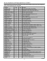
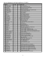
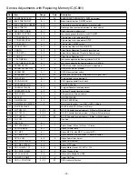
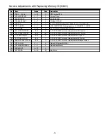
Service Adjustments with Replacing Memory IC(IC801)
(/JE0318C)
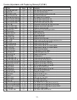
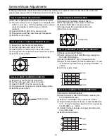
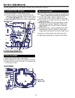
Following table shows the initial values which have been stored in the CPU ROM, and items for the service adjustments.
Service mode adjustments table in CPU ROM
No.
Item
Range
Data
Description
01
VIF VCO ADJ
0 ~ 3F
1E
VIF VCO free-running frequency fine adjustment
02
STRAP ADJ
0 ~ 3F
9
SOUND trap free-running frequency fine adjustment
03
H VCO ADJ
0 ~ F
08
HORIZONTAL VCO free running frequency fine adjustment
04
SECAM BLK LEVEL (R)
0 ~ 3F
33
SECAM-(R-Y) signal black level adjustment
05
SECAM BLK LEVEL (B)
0 ~ 3F
11
SECAM-(B-Y) signal black level adjustment
06
V SIZE 50
0 ~ 3F
34
V Ramp amplitude adjustment (Vertical Size) for PAL
07
V-SIZE 50 ZOOM
0 ~ 3F
0
V-Size for Zoom Mode PAL
08
V-SIZE 50 WIDE
0 ~ 3F
0
V-Size for Wide Mode PAL
09
V-SIZE 60
-1F ~ 20
0
V Ramp amplitude adjustment (Vertical Size) for NTSC
10
V SIZE 60 ZOOM
-1F ~ 20
0
V-Size for Zoom Mode NTSC
11
V SIZE 60 WIDE
-1F ~ 20
0
V-Size for Wide Mode NTSC
12
V S CORRECT 50
0 ~ 3F
22
V-S Correction control for PAL
13
V S CORRECT 60
-1F ~ 20
-6
V-S Correction control for NTSC
14
V LINEARITY 50
0 ~ 3F
23
V Linearity control for PAL
15
V LINEARITY 60
-1F ~ 20
3
V Linearity control for NTSC
16
V SHIFT 50
0 ~ F
4
V Ramp start timing point adjustment 2 line/step (V position) for PAL
17
V SHIFT 60
-7 ~ 8
-3
V Ramp start timing point adjustment 2 line/step (V position) for NTSC
18
AFC2 H PHASE 50
0 ~ 1F
F
Horizontal Phase (H-Position) adjustment for PAL
19
AFC2 H PHASE 60
-0F ~ 10
02
Horizontal Phase (H-Position) adjustment for NTSC
20
CONTRAST CONTROL
0 ~ 2F
1F
Contrst Control (Offset Data)
21 BRIGHTNESS CONTROL
0 ~ 3F
33
Brightness Control (Offset Data)
22
TINT CONTROL TV
-3F ~ 40
0
Tint Control (Offset Data) for TV
23
TINT CONTROL AV
-3F ~ 40
0
Tint Control (Offset Data) for AV
24
SERVICE SW
0 ~ 1
0
Vertical Output ON/OFF Switch (Contrast Control)
25
VRAMP OFF
0 ~ 1
0
Vertical Output ON/OFF Switch ON/OFF
26
V AGC SPEED UP
0 ~ 1
0
V Ramp AGC Speed
27
Y/C TEST ON
0 ~ 1
0
28
HVCO FREERUN UP
0 ~ 1
0
Horizontal free-running frequency up
29
HALF H KILLER
0 ~ 1
0
Composite-Sync Half H Kill
30
H FREE
0 ~ 1
0
Horizontal forced free-running mode switch
31
H START
0 ~ 1
0
Horizontal output switch
32
AFC1 PULL UP
0 ~ 1
1
Horizontal AFC1 gain switch
33
HVCO PULL UP
0 ~ 1
0
Horizontal VCO Filter PULL UP
34
HVCO PULL DOWN
0 ~ 1
0
Horizontal VCO Filter PULL DOWN
35
AFC1 GAIN UP
0 ~ 3
0
Horizontal AFC1 gain switch
36
ACFQ IF CONT
0 ~ 1
1
AFC1 gain controlled by IF AGC
37
DOUBLE COINCI
0 ~ 1
0
Horizontal AFC1 Gain Controlled by FAST Horizontal Coincidence
38
AFC2 RAMP UP
0 ~ 1
0
AFC2 RAMP UP
39
FBP BTHL
0 ~ 1
0
FBP slice level switch
40
AFC2 GAIN UP
0 ~ 3
3
Horizontal AFC2 gain switch
41
HBLK RIGHT
0 ~ 3
1
Control edge of horizontal blanking pulse that is right side of picture
42
HBLK LEFT
0 ~ 3
0
Control edge of horizontal blanking pulse that is left side of picture
43
HBLK SEL
0 ~ 1
1
Horizontal blanking select
44
HD SEL
0 ~ 1
1
Horizontal time pulse for OSD
45
HV BLK OFF
0 ~ 1
0
H and V blanking off switch for RGB-OUT
46
BGP SHIFT
0 ~ 3
0
Burst Gate Pulse for Position Adjustment
SM_21-BD6V(AC7-A)Aus 11/8/07 1:14 PM Page 9
Содержание CP21VF1
Страница 35: ... 35 ...
Страница 36: ...SANYO Electric Co Ltd Nov 07 30 CPS Printed In Indonesia ...


