


-18-
C4EV
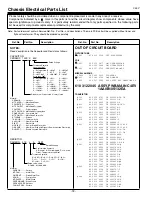
OUT OF CIRCUIT BOARD
PICTURE TUBE
Q901 414 010 1108 CRT A34KPU02XX
COIL
L901 645 051 5477 COIL,DEGAUSSING
645 051 5484 COIL,DEGAUSSING
L902 645 027 5739 DEFLECTION YOKE
MISCELLANEOUS
SP901 645 063 4635 SPEAKER,8
W901 645 048 2106 CORD,POWER
W902 610 297 9565 ASSY,WIRE GND CONECTOR F8
610 312 2045 ASSY,PWB,MAIN C4EV
1AA0B10S132EA
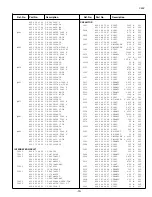
TRANSISTOR
Q111 405 015 9701 TR 2SC2814-F4-TB
Q431 405 018 0507 TR 2SC3332-R
405 018 0606 TR 2SC3332-S
Q432 406 017 1809 TR TT2138LS-YB11
Q611 405 013 6801 TR 2SC2274-E
405 013 7006 TR 2SC2274-F
Q612 405 013 6801 TR 2SC2274-E
405 013 7006 TR 2SC2274-F
Q613 405 171 4107 TR 2SK2647
Q614 405 006 6504 TR 2SA984-E
405 006 6702 TR 2SA984-F
Q631 405 014 4509 TR 2SC2412K T146 R
405 014 4608 TR 2SC2412K T146 S
405 015 8704 TR 2SC2812-L6-TB
405 015 8902 TR 2SC2812-L7-TB
405 173 9803 TR 2SC3928A1R
405 173 9902 TR 2SC3928A1S
Q661 405 059 9903 TR 2SD1913-R-RA
405 060 0005 TR 2SD1913-S-RA
Q681 405 011 8401 TR 2SC1740S-Q
405 011 8500 TR 2SC1740S-R
405 011 8609 TR 2SC1740S-S
405 012 2002 TR 2SC1815-GR
405 012 2101 TR 2SC1815-O
405 012 2309 TR 2SC1815-Y
405 020 7501 TR 2SC945A-PA
405 020 7709 TR 2SC945A-QA
405 020 7907 TR 2SC945A-RA
Q683 405 089 0000 TR 2SA1707-S
405 089 0109 TR 2SA1707-T
405 009 6907 TR 2SB985-S
405 009 7003 TR 2SB985-T
Q684 405 011 8401 TR 2SC1740S-Q
405 011 8500 TR 2SC1740S-R
405 011 8609 TR 2SC1740S-S
405 012 2002 TR 2SC1815-GR
405 012 2101 TR 2SC1815-O
!
!
!
!
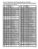
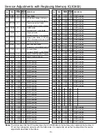
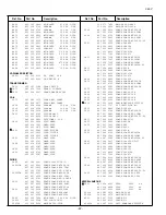
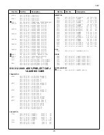
Chassis Electrical Parts List
Ref. No.
Part No.
Description
Ref. No.
Part No.
Description
Product safety should be considered when a component replacement is made in any area of a receiver.
Components indicated by a
mark in this parts list and the circuit diagram show components whose value have
special significance to product safety. It is particularly recommended that only parts specified on the following parts
list be used for components replacement pointed out by the mark.
!
Note: Parts order must contain Service Ref. No., Part No., and descriptions. The main PCB unit will be supplied without tuner and
flyback transformer. They should be ordered separately.
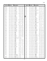
Read description in the Capacitor and Resistor as follows:
CAPACITOR
CERAMIC 100P K 50V
Rated Voltage
Tolerance Symbols:
Less than 10pF
A : Not specified B :
±
0.1pF
C :
±
0.25pF
D :
±
0.5pF
F :
±
1PF
G :
±
2pF
R :
±
0.25-0pF
S :
±
0-0.25pF
E : +0-1pF
More than 10pF
A : Not specified B :
±
0.1%
C :
±
0.25%
D :
±
0.5%
F :
±
1%
G :
±
2%
H :
±
3%
J :
±
5%
K :
±
10%
L :
±
15%
M :
±
20%
N :
±
30%
P : +100-0%
Q : +30-10%
T : +50-10%
U : +75-10%
V : +20-10%
W : +100-10%
X : +40-20%
Y : +150-10% Z : +80-20%
Rated value: P=pico farad, U=micro farad
Material:
CERAMIC........... Ceramic
MT-PAPER......... Metallized Paper
POLYESTER...... Polyester
MT-POLYEST.....Metallized Polyester
POLYPRO.......... Polypropylene
MT-POLYPRO....Metallized Polypropylene
COMPO FILM.....Composite film
MT-COMPO........Metallized Composite
STYRENE...........Styrene
TA-SOLID........... Tantalum Solid
AL-SOLID........... Aluminium Solid
ELECT................ Electrolytic
NP-ELECT..........Non-polarised Electrolytic
OS-SOLID.......... Aluminium Solid with Organic Semiconductive Electrolytic
DL-ELECT.......... Double Layered Electrolytic
RESISTOR
CARBON 4.7K J A 1/4W
Rated Wattage
Performance Symbols:
A: General B: Non flammable Z: Low noise
Other: Temperature coefficient
Tolerance Symbols:
A:
±
0.05% B:
±
0.1% C:
±
0.25% D:
±
0.5%
F:
±
1% G:
±
2% J:
±
5% K:
±
10%
M:
±
20% P: +5-15%
Rated value, ohms:
K: 1,000, M: 1,000,000
Material:
CARBON........... Carbon
MT-FILM............ Metal Film
OXIDE-MT......... Oxide Metal Film
SOLID................ Composition
MT-GLAZE......... Metal Glaze
WIRE WOUND... Wire Wound
CERAMIC RES.. Ceramic
FUSIBLE RES.... Fusible
NOTES: