Sanyo CP14G1 Скачать руководство пользователя страница 10

-10-

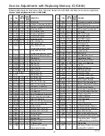
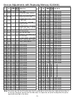
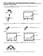
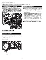
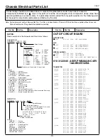
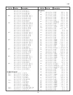
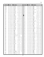
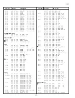
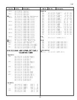
Service Adjustments with Replacing Memory IC(IC802)

Notes:

The initial value that the CPU writes down the CPU ROM data to the memory when replaced the memory IC.
TV set may not operate correctly with this initial value. It is required to set up the fine adjustment for service 
adjustments described in the above.

DATA

INITIAL

No.

ITEM

RANGE

SETUP

DESCRIPTION

DATA

86

TUNER

0,1

0

Tuner Option

87

AV123

0~3

0

AV1/AV2/AV3 Option, 0=AV only, 

1=AV1, AV2, 2~3=AV1, AV2,AV3

88

OPT POS

0,1

1

Programme number Option, 

Position No. Option, 0=100 pos., 1=256 pos.

89

GAME

0,1

1

GAME Option, 

0=without GAE, 1=with GAME

90

LANGUAGE

0,1

1

Language Option, 

0=without Language, 1=with Language

91 OPT COL

0~7

2

Colour System Option, 0~1=PAL only,

2=VMT, 3=China/Indonesia, 4=3 System, 5~7=Multi

92

OPT SIF

0~7

0

SIF System Option

93

OPT BASS

0~3

0

Bass Expander Option,

0=without BASS, 1~2=BASS EXPANDER, 3=WOOFER

94

OPT SURR

0,1

0

Surround Option, 

0=without SURROUND, 1=with SURROUND

95

SUB-BT

0,1,2

0

Audio IC (NJW1142)Sub Bass Treble adj.

96

A-AGC

0,1,2

0

Audio IC (NJW1142) AGC adj.

300

R00

0~255

154

ROM Correction

301

R01

0~255

242

ROM Correction

302

R02

0~255

166

ROM Correction

303

R03

0~255

246

ROM Correction

304

R04

0~255

3

ROM Correction

305

R05

0~255

0

ROM Correction

306

R06

0~255

0

ROM Correction

307      R07

0~255

0

ROM Correction

308

R08

0~255

2

ROM Correction

309

R09

0~255

229

ROM Correction

310

R10

0~255

144

ROM Correction

311

R11

0~255

13

ROM Correction

312

R12

0~255

239

ROM Correction

313

R13

0~255

141

ROM Correction

314

R14

0~255

238

ROM Correction

315

R15

0~255

141

ROM Correction

316

R16

0~255

237

ROM Correction

317

R17

0~255

141

ROM Correction

318

R18

0~255

236

ROM Correction

319

R19

0~255

141

ROM Correction 

320

R20

0~255

235

ROM Correction

321

R21

0~255

141

ROM Correction

322

R22

0~255

33

ROM Correction

323

R23

0~255

155

ROM Correction

324

R24

0~255

6

ROM Correction

325

R25

0~255

33

ROM Correction

DATA

INITIAL

No.

ITEM

RANGE

SETUP

DESCRIPTION

DATA

326

R26

0~255

154

ROM Correction

327

R27

0~255

246

ROM Correction

328

R28

0~255

0

ROM Correction

329

R29

0~255

0

ROM Correction

330

R30

0~255

0

ROM Correction

331

R31

0~255

0

ROM Correction

332

R32

0~255

0

ROM Correction

333      R33

0~255

0

ROM Correction

334

R34

0~255

0

ROM Correction

335

R35

0~255

0

ROM Correction

336

R36

0~255

0

ROM Correction

337

R37

0~255

0

ROM Correction

338

R38

0~255

0

ROM Correction

339

R39

0~255

0

ROM Correction

340

R40

0~255

107

ROM Correction

341

R41

0~255

127

ROM Correction

342

R42

0~255

7

ROM Correction

343

R43

0~255

3

ROM Correction

344

R44

0~255

234

ROM Correction

345

R45

0~255

144

ROM Correction 

346

R46

0~255

3

ROM Correction

347

R47

0~255

33

ROM Correction

348

R48

0~255

166

ROM Correction

349

R49

0~255

249

ROM Correction

350

R50

0~255

33

ROM Correction

351

R51

0~255

167

ROM Correction

352

R52

0~255

34

ROM Correction

353

R53

0~255

0

ROM Correction

354

R54

0~255

0

ROM Correction

355

R55

0~255

0

ROM Correction

366

R12

0~255

0

ROM Correction

367

R13

0~255

0

ROM Correction

368

R68

0~255

0

ROM Correction

369

R69

0~255

0

ROM Correction

370

R70

0~255

0

ROM Correction

371

R71

0~255

0

ROM Correction

372

R72

0~255

160

ROM Correction

Содержание CP14G1

Страница 1: ...mensions 370 8 W 348 6 H 384 4 D mm Weight approx 8 7 Kg Specifications subject to change without notice Original Version Chassis Series AC5 G C4EV FILE NO Model No CP14G1 A Australia Give complete SERVICE REF NO for parts order or servicing It is shown on the rating plate at the cabinet back of the unit This T V receiver will not work properly in foreign countries where the television transmissio...

Страница 2: ...ON PRECAUTION The primary source of X RADIATION in television receiver is the picture tube The picture tube is specially con structed to limit X RADIATION emissions For continued X RADIATION protection the replacement tube must be the same type as the original including suffix letter Excessive high voltage may produce potentially hazardous X RADIATION To avoid such hazards the high voltage must be...

Страница 3: ...G OUT B OUT H OUT V OUT 19 20 21 27 23 IC201 IF VIDEO CHROMA MUTE AUDIO IN AUDIO OUT IC001 AUDIO AMP MONO IC281 SECAM 6 7 Low B 5V 2 TELETEXT UNIT TEXT R TEXT G TEXT B TEXT BLK 180V VIDEO IN 14 SECAM KILLER 1 5 IC501 VERT DEF SWITCH VR631 130V Reg Reg 24V 15V 9V 5VRC Reg Reg 24V Protect T431 H DRIVE TRANS Q432 H OUT 25V 130V B G R 9V H V L902 DY AFC ABL T471 FBT Q901 CRT Heater HV 180V Heater Low ...

Страница 4: ...e High OSD GREEN OUT Active High OSD BLUE OUT Active High DEFLECTION CIRCUIT HORIZ SYNC IN ACTIVE LOW VERT SYNC IN ACTIVE LOW POWER PROTECT IN POWER ERROR LOW POWER CIRCUIT etc SCL SDA IC802 MEMORY OSC X801 32 768KHz CPU OSC OUT CPU OSC IN LED ON TIMER LED OUT ON TIMER ON Low RC SIGNAL IN ACTIVE HIGH RC PRE AMP IC001 AUDIO AMP MONO A101 F S TUNER AFT SIGNAL INPUT 10 RESET INPUT ACTIVE LOW 13 MUTE ...

Страница 5: ...CLMP V C VCC 5V 46 47 48 49 50 A2C PLL 51 52 53 54 Audio Output FM Output Selected Audio Output PIF AGC RF AGC Output PIF Input1 PIF Input 2 IF Ground IF Vcc FM Filter AFT Output Bus Data Bus Clock ABL Red Input Green Input Blue Input Fast Blanking Input RGB Vcc Red Output Green Output Blue Output fsc output or C Sync output Vertical Output Ramp ALC Filter Horizontal BUS Vcc Horizontal Output Hori...

Страница 6: ... 3bit Amp 54 10p SIF In Sound BPF VCO Coil VCO COIL1 VCO COIL2 48 49 VIF VCO Chroma Counter B N INV IF Ident OSC C D Amp SIF Sys 2bit pre scaller SIF VCO 500K BPF SIF APC Filter 1K 0 01u 1000p 53 LIM AMP FM Det FM Level 5bit Chroma C D APC Det 500K Det To BUS Chroma VCO VIF Counter Reset Pulse VCO Ident VIF Sys 2bit Phase Detector A MUTE 1bit VOLUME D A VOLUME Filter A SW 1bit Input Select VOLUME ...

Страница 7: ...oes to the stand by mode When an abnormality occurs during TV reception it causes pin 27 of the CPU to go continually Low less than 0 75V for about one second The CPU detects that this has occurred and outputs the signal from pin 31 to switch off the power supply lines Releasing the protective circuit and restoring power supply To release the protective circuit and restore power supply turn the po...

Страница 8: ...MME UP on the TV set while the above On Screen Display is still on the screen The following picture appears on the screen This completes the initialization of memory IC Following shows the initialized contents of memory data by this procedure Plug Play No executed Inhibit Data Cancelled Ch Skip Data Cancelled Sound Volume Data 10 63 steps Volume Lock OFF Tuning Lock OFF Music Mode OFF AV Start OFF...

Страница 9: ...shows the initial values which have been stored in the CPU ROM and items for the service adjustments Service mode adjustments table in CPU ROM DATA INITIAL No ITEM RANGE SETUP SCRIPTION DATA 43 PORS 0 3 2 Pre shoot Over shoot Adj in AV mode 44 RFCO 0 3 0 RF Coring Gain Adj 45 PORWN 0 1 0 Switching of RF Pre shoot and Over shoot 46 PORSN 0 3 0 RF Pre shoot Over shoot Adj 47 TINT 16 15 0 RF Tint Adj...

Страница 10: ...ection 313 R13 0 255 141 ROM Correction 314 R14 0 255 238 ROM Correction 315 R15 0 255 141 ROM Correction 316 R16 0 255 237 ROM Correction 317 R17 0 255 141 ROM Correction 318 R18 0 255 236 ROM Correction 319 R19 0 255 141 ROM Correction 320 R20 0 255 235 ROM Correction 321 R21 0 255 141 ROM Correction 322 R22 0 255 33 ROM Correction 323 R23 0 255 155 ROM Correction 324 R24 0 255 6 ROM Correction ...

Страница 11: ...V S Correction adjustment Read Status Item No Item Data value Display for RF AGC RF AGC adjustment Read Status Item No Item Data value Data value for Red Display for DRV White balance adjustment Read Status Item No Item Data value for Blue To return to normal TV mode press the MENU button on the TV set or the remote control handset 2 Select item by pressing the TIMER Item No UP or SOUND MUTE Item ...

Страница 12: ...RIZONTAL CENTRE Horizontal centre 1 Receive a monochrome circular pattern 2 Set the brightness and contrast to maximum 3 Select V SIZ in the service mode 4 Change value to be optimum vertical size 5 Exit from service mode Item 04 V SIZ VERTICAL SIZE 1 Receive a crosshatch pattern 2 Select a picture mode of NATURAL by pressing the PICTURE MODE button 3 Select V SCO in the service mode 4 Adjust Vert...

Страница 13: ...s in this mode 7 Select Item 21 DRV mode to enter the white balance adjusting mode 8 Press the 3 Red Drive 4 Red Drive Blue Drive or RECALL Blue Drive button alternately to produce normal black and white picture 9 Exit from the service mode 10 Check for proper grey scale tracking at all brightness levels NOTE If the grey scale adjustment is made after picture tube replacement check the high voltag...

Страница 14: ...J604 T611 H14 C607 H1 C607 C607 H2 C608 D613 R618 D610 J605 L605 KG 3 2 C628 A F601B T611 H2 T611 H10 T611 H7 TP EE C610 5 L441 L441A L441 H3 C43 R441 R435 C437 C435 H3 C435 H2 C44 C44 D441 C441 H2 C441 H3 C441 H4 R435A H1 J435 Q661 E B D605 C605 D603 H2 D606 C606 J603 H1 H3 H4 C603 D604 C604 TP B R665 J607 Q613 Q613 H2 Q613 H3 R605 R613 H1 R613 H2 C608A R628 R629 R617 C611A C629 C R643 JP4 C646 D...

Страница 15: ...cial function ON by pressing the VOLUME or button To cancel set to OFF 2 Tuning Lock setting The following special functions can be set up on this TV set With this function a maximum sound volume limit can be set at any level 3 Music Mode setting When Music Mode is ON Programme position from 91 to 99 and 0 are set Music Mode Only sound is provided and any picture is not on the screen under Music M...

Страница 16: ...rs to check this use bias controls Readjust the yoke position if necessary until all screens are pure 7 Adjust each Bias control and screen control to obtain white raster Refer to Gray Scale Adjustment If part of the picture screen is coloured adjust the Deflection Yoke position forward or backward slightly 8 Tighten the mounting screw of the Deflection Yoke Adjust Convergence next CENTRE CONVERGE...

Страница 17: ... RC BATTERY LID 10 610 011 6405 ROD ANTENNA ASSY or 610 216 4886 ROD ANTENNA ASSY or 610 217 1006 ROD ANTENNA ASSY or 645 012 0428 ROD ANTENNA ASSY or 645 042 4519 ROD ANTENNA ASSY 11 645 003 2837 ANT MATCHING BOX or 610 230 3216 ANT MATCHING BOX 610 311 2404 INSTRUCTION MANUAL C4EV Key No Part No Description Key No Part No Description Note Parts order must contain Service Ref No Part No and descr...

Страница 18: ...SANYO Electric Co Ltd A14800 Oct 03 30 BB Printed in Japan ...

Страница 19: ...ade in any area of a receiver Components indicated by a mark in this parts list and the circuit diagram show components whose value have special significance to product safety It is particularly recommended that only parts specified on the following parts list be used for components replacement pointed out by the mark Note Parts order must contain Service Ref No Part No and descriptions The main P...

Страница 20: ... 25V C004 404 084 9209 ELECT 4 7U M 50V 403 051 0607 ELECT 4 7U M 50V C005 404 089 7200 ELECT 100U M 25V 403 044 9501 ELECT 100U M 25V C006 404 087 5109 ELECT 470U M 25V 403 047 5005 ELECT 470U M 25V C007 403 057 3107 POLYESTER 0 1U K 50V 403 181 8207 POLYESTER 0 1U K 50V C008 404 084 8400 ELECT 1000U M 25V 403 045 1504 ELECT 1000U M 25V C012 403 215 2201 CERAMIC 0 01U K 50V C1001 404 084 8905 ELE...

Страница 21: ...50V C629 404 073 2709 CERAMIC 2200P M 250V 404 073 2808 CERAMIC 2200P M 250V C631 403 247 5003 CERAMIC 470P K 1K 403 269 1809 CERAMIC 470P K 1K C633 403 247 5003 CERAMIC 470P K 1K 403 269 1809 CERAMIC 470P K 1K C634 403 247 5003 CERAMIC 470P K 1K 403 269 1809 CERAMIC 470P K 1K C641 404 080 0606 ELECT 100U M 160V C643 404 084 9506 ELECT 470U M 35V 403 054 1502 ELECT 470U M 35V C644 404 084 8400 ELE...

Страница 22: ...6 9103 OXIDE MT 27 JA 2W R605 401 010 9203 CARBON 560K JA 1 2W R606 401 027 0507 CARBON 470K JA 1 6W R607 401 019 9600 CARBON 47 JA 1 4W R609 401 025 8208 CARBON 22K JA 1 6W R611 401 025 8208 CARBON 22K JA 1 6W R612 402 001 8502 FUSIBLE RES 10 J 1 2W R613 401 064 3806 OXIDE MT 1 0 JA 2W R615 401 016 1508 CARBON 22 JA 1 4W R616 401 024 7400 CARBON 10K JA 1 6W R617 402 001 8106 FUSIBLE RES 680 J 1 4...

Страница 23: ... 181B 51 D1910A 610 264 5064 HOLDER LED S2CP 610 273 7929 HOLDER LED S4KF 610 303 9954 HOLDER LED C4LA D249 407 099 6003 ZENER DIODE MTZJ9 1B 407 057 9701 ZENER DIODE RD9 1EB2 D352 407 063 8705 ZENER DIODE MTZJ5 1C 407 056 9801 ZENER DIODE RD5 6EB1 408 047 7103 ZENER DIODE MTZJ5 1C 52 D357 407 005 4505 DIODE DS442X 408 008 2406 DIODE 1N4148 407 012 4406 DIODE 1SS133 407 013 4306 DIODE 1S2076A 407 ...

Страница 24: ... 2 405 040 5600 TR 2SC2228 D 405 029 6901 TR 2SC2228 E Q721 405 001 7407 TR 2SA1015 O SAN 405 001 7605 TR 2SA1015 Y SAN Q751 405 002 0308 TR 2SA1037K T146 R 405 002 0407 TR 2SA1037K T146 S 405 002 6706 TR 2SA1179 M6 TB 405 002 6904 TR 2SA1179 M7 TB 405 173 9605 TR 2SA1235A1E 405 173 9704 TR 2SA1235A1F CAPACITOR C708 404 084 6505 CERAMIC 1000P K 2K 403 077 2708 CERAMIC 1000P P 2K 403 077 2807 CERAM...

Страница 25: ...000KK470 CRD NH 1SJ270 RD10EB2 MTZJ10B DZXLBZA10B EM1 EM1LBWA AE 1K AA EM1 EM1LBWA 1 16GJ 22KC 160EM100X 1000KK470 CRD NH RD6 8EB1 MTZJ6 8A DZXLBZA6 8A 1 16GJ 560KC 22K RU3AM ZZ0122 B4Z21B0150N Z21B0340N 1SJ27K DJ12K 1 16GJ 10KC X 2400030 AH AJ 2400030 2400030 25EM470 25EM470LBWA 16EM22 16EM22LBWAJ 47K 100K 3 9K 1 16GJ 10KC X 1 16GZ 0C 1 16GZ0C J10AM050N X 1 16GJ 1KC 8 2K 8 2K 8 2K 100 100 1 16GJ4...

Страница 26: ...1 Q681 J401 Q684 R689 R688 D682 C210 R212 C232 C231 C233 C209 C246 C205 C1902 C517 C527 R211 R357 J513 R243 D249 C510 R510 R511 J504 D352 R352 J502 J506 C006 C004 C003 C005 C008 IC001 H1 IC001 H2 D861 C893 C861 C805 X801 IC802 R869 R866 J802 J804 J806 R818 R872 J1903 J1202 J017 J016 J403 R855 R851 R853 R857 J819 J809 J011 J049 J009 J024 J021 R351 J808 R644 H2 R644 H1 R644 R642 R682 J687 J622 J621 ...

Отзывы: