


Page 40
brake mixing
Function Page 2 (BR-MIX)
The Brake Mixing function is used primarily with 1/5th scale gas-powered models or other types of models that use two separate
brake servos. Brake servo Delay can be set for the 2nd channel brake, the 3rd channel brake, or the 4th channel brake either
independently or at the same time. This allows you to adjust when each brake is engaged. For example, if your model features
separate front and rear brakes, the rear brake can be adjusted to engage before the front brake engages or vice-versa.
E
FB
RB
E
E
E
RB
RB
RB
FB
FB
FB
CH2 CH3
CH2 CH4
CH2 CH3 CH4
CH2 CH3 CH4
CH1 Steering
CH1 Steering
CH3 Auxiliary
CH1 Steering
CH1 Steering
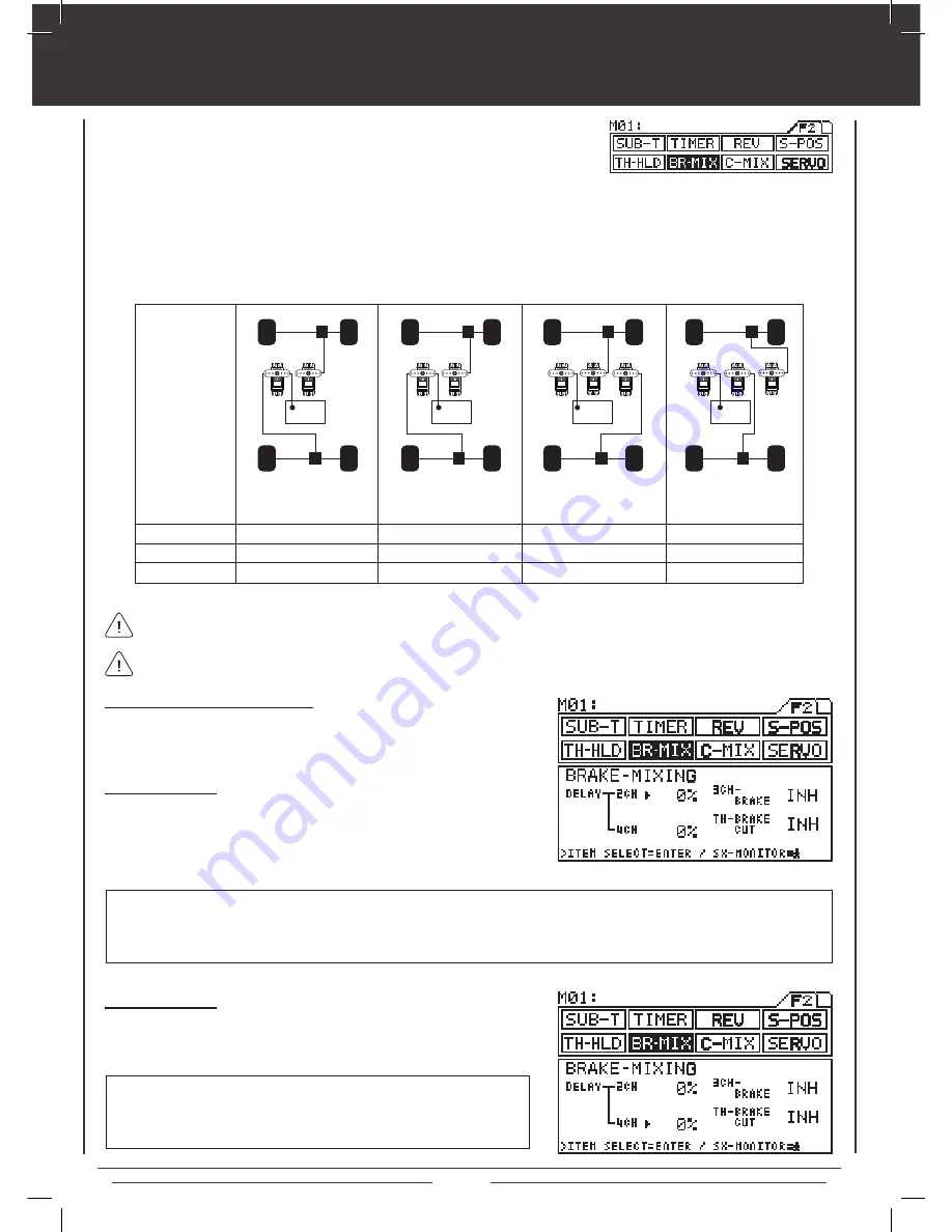
Brake Mixing
settings for
various
model types.
E=Engine
FB=Front Brake
RB=Rear Brake
4 Channel
INH
INH
4 Channel
ACT
ACT
4 Channel
ACT
ACT
3 or 4 Channel
ACT
INH
Receiver Type
3CH Brake
TH-Brake Cut
2CH Delay Setting
1) Press the Function key to highlight the BR-MIX menu. The cursor will
default to 2CH in the Programming Window.
2) Press INC/+ or DEC/- keys to adjust the desired 2CH DELAY value.
BR-MIX 2CH DELAY setting range is 0% to 100%. The default setting is 0%. The 2CH DELAY setting controls the speed of the
Brake Side of the throttle servo. When the value is increased the speed of the Brake Side of the throttle servo is slowed while
the speed of the 4th channel brake servo remains normal. This results in the 4th channel brake servo reaching its End Point
before the Brake Side of the throttle servo reaches its End point.
4CH Delay Setting
1) Press the ENTER key to move the cursor to 4CH in the Programming
Window, then press INC/+ or DEC/- keys to adjust the desired 4CH
DELAY value.
BR-MIX 4CH DELAY setting range is 0% to 100%. The default setting is
0%. The 4CH DELAY setting controls the speed of the 4th channel brake
servo. When the value is increased the speed of the 4th channel brake
servo is slowed.
Before making adjustments to the different
Brake Mixing values, you must first make servo Reversing (REV), servo End
Point Adjustments (EPA), and servo Sub-Trim adjustments (SUB-T) to your 3rd and/or 4th channel brake servos.
Making different adjustments to the DELAY value of the 2nd, 3rd, and 4th channel brake servos will result in a number of
different combinations (mixing) of braking action to suit your particular setup.
With Transmitter Set to 4CH Mode
The transmitter should be set to 4CH Mode to ensure the greatest Brake
Mixing functionality. See page 47 for more information.
Содержание M11X
Страница 1: ...OPERATING MANUAL 670A12978A ...
Страница 67: ...Page 67 notes ...