


DRAWING No.EM7000 09-1306 2040 2040
— 38 —
6-4-2 ±DCV (±DCV ) Maximum measurable voltage DC±600 V
1) Objects of measurement
Voltages of DC circuits where positive voltage and negative
voltage are present on the reference such as IC circuits.
2) Measuring ranges (8 ranges)
±0.15/±0.6/±1.5/±6/±15/±60/±150/±600 V
3) Measurement procedure
0
A
•
V
C
D
±
+
-
-
-
+
+
Rf100k
Rc9.1k
2
8
1
4
3
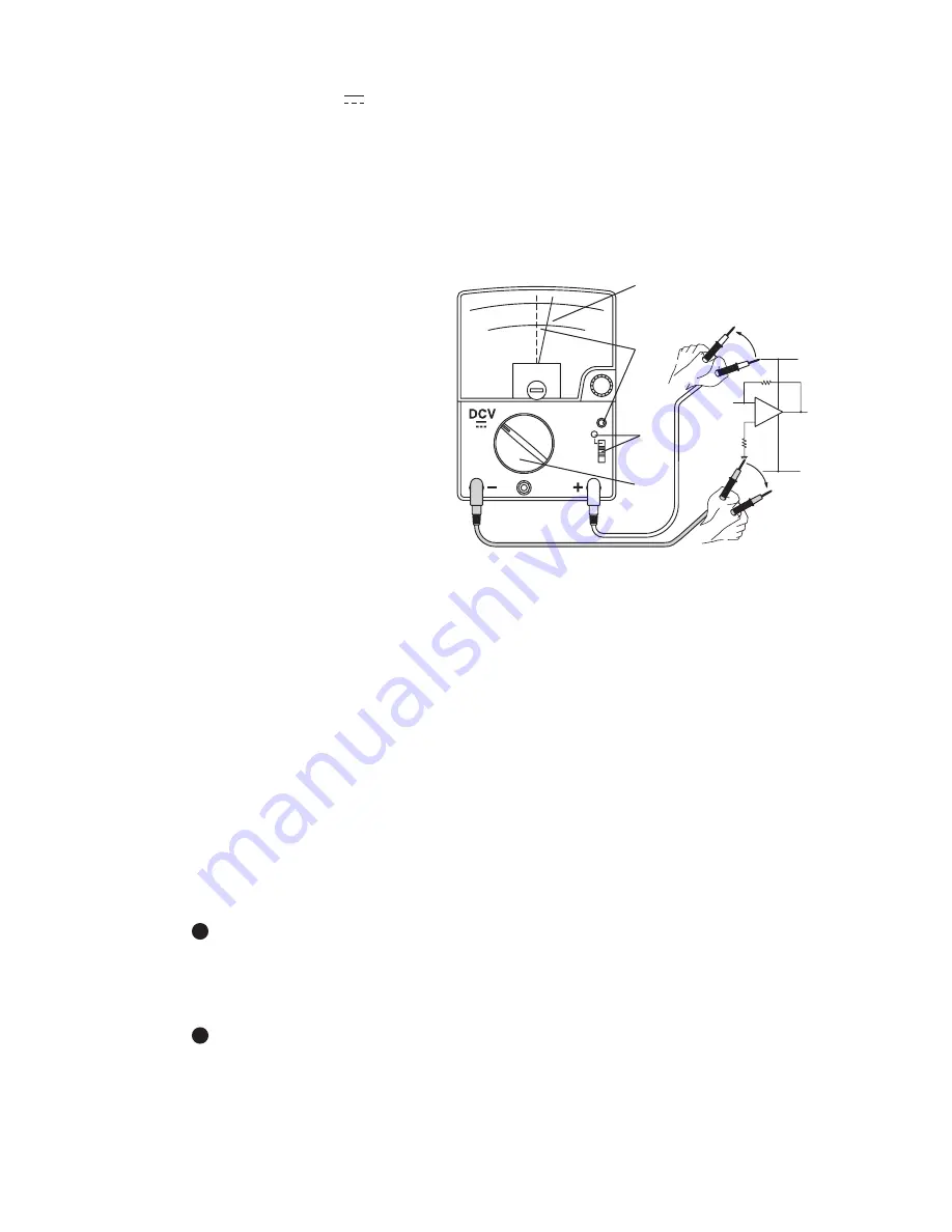
Insert the red plug of
test leads into the
+input terminal, and the
black plug into the
–COM terminal.
Turn the function/range
selector to the appropriate
blue ±DCV range at upper
left.
Turn on the power
switch (power ON :
Lamp blinks).
Turn the electrical zero adjuster (ZERO ADJ) to adjust the
pointer to the zero position at the center of blue ±DCV
•
A scales.
Apply the black test pin to the reference measures point, and
the red test pin to the desired measuring point.
Read the indication on the ±DCV
•
A scales in a unit of V (volt).
If the indication is on the right side of the zero position, the red
test lead is on the positive potential (voltage), and the black test
lead is on the negative potential (voltage).
If the indication is on the left side of the zero position, the red
test lead is on the negative potential (voltage), and the black
test lead is on the positive potential (voltage).
Detach the test pins from the circuit to be measured.
Turn off the power switch (power OFF: Lamp blinking goes off).
Before measurement, make sure that the meter pointer is
adjusted correctly to the zero position at the center of
±DCV
•
A scales.
If shifted, an indication error occurs by the amount of shift.
The zero meter position of the functions expect ±DCV and
±DCA functions is at the left end of black DCV
•
A scales.
EM7000_08_英_再校 13.6.10 1:26 PM ページ12
Содержание EM7000
Страница 1: ...EM7000 FET電子テスタ FET MULTITESTER 取扱説明書 INSTRUCTION MANUAL ...
Страница 2: ......
Страница 63: ...MEMO ...
Страница 64: ...MEMO ...
Страница 66: ......
Страница 67: ......