


DRAWING No.EM7000 09-1306 2040 2040
— 35 —
[6] MEASURING PROCEDURE
6-1 Startup Inspection (See the flowchart on the next page.)
1. To prevent an electric shock, do not use the tester if the tester
itself or test leads are damaged.
2. Make sure that the test leads are not broken or the fuses are not
blown.
WARNING
6-2 How to select an appropriate range
Voltage (DCV, ±DCV, ACV (rms), ACV (p-p), Current (DCA, ±DCA)
As a rule, select the range whose maximum scale value is larger
than the value to be measured.
For example, when measuring the voltage of 9 V, the measuring
range should not be 3 V range or 30 V range but be 12 V range,
and when measuring 15 V, it should be 30 V range.
Resistance (
Ω
)
Select the range in which the pointer indicates the approximate
center of the
Ω
scales.
6-3 Preparation for Measurement
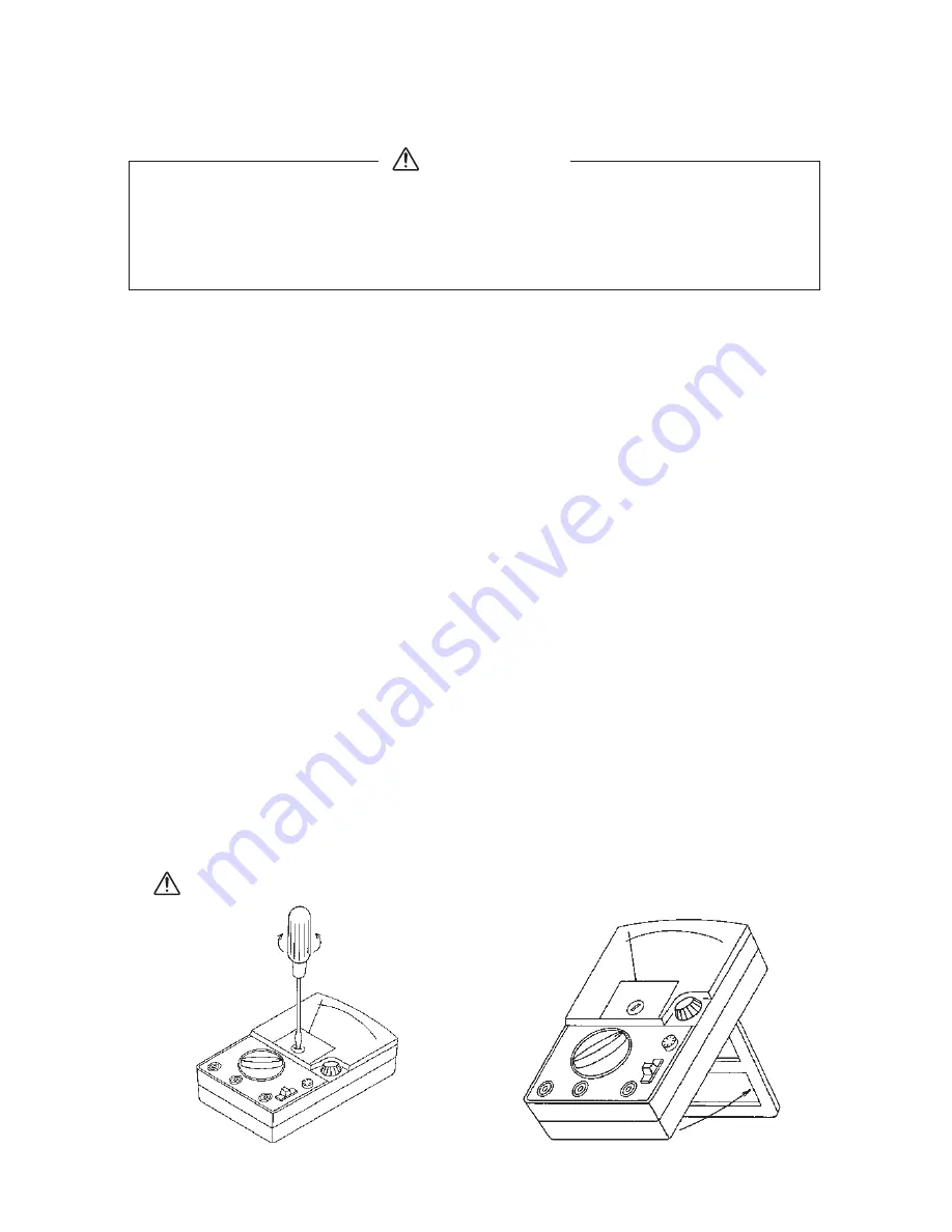
If the pointer does not indicate correctly the zero position at the left end
of the scale plate, turn the mechanical zero meter adjuster with a
screwdriver to adjust it. (See the figure below.)
Connect the test leads to the input terminals, and select the desired
function/range with the function/range selector.
Turn on the power switch (power ON), and turn the electrical zero
meter adjuster (ZERO ADJ) to adjust the electrical zero meter position.
Adjust the pointer to the zero position at the center of the meter for the
±DCV and ±DCA functions, and to the zero position at the left end of
the meter for other functions.
Do not touch the electrical zero meter adjuster during measurement.
How to Use
the Stand
Mechanical zero
position adjustment
EM7000_08_英_再校 13.6.10 1:26 PM ページ9
Содержание EM7000
Страница 1: ...EM7000 FET電子テスタ FET MULTITESTER 取扱説明書 INSTRUCTION MANUAL ...
Страница 2: ......
Страница 63: ...MEMO ...
Страница 64: ...MEMO ...
Страница 66: ......
Страница 67: ......