background image

Autofill

 System Installation


1. Connect 

the 

premix

 line from the remote fill sys-

tem to the 3/8" barbed fitting located at the rear 
of the remote dispensing head. 

Oetiker®


clamps are required to contain the working 
pressures of the system. Pressurize the line. 

2. Activate 

the 

autofill

 system by pressing the fill 

switch located on the front panel of the dispens-
ing head 

3.  Purge the line by allowing the mix pan to fill until 

the 

system

 probes close the fill switch solenoid 

valve. 


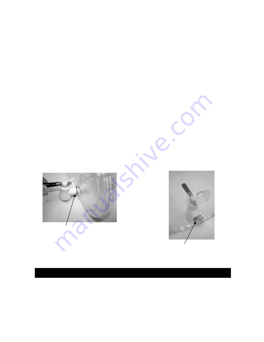
Assemble gasket on spigot side. 

Warning: Machine damage possible if nut installed incorrectly!  

Lubricate flat side of nut with Sani-Gel. 
Install flat side of nut toward spigot. 

Spigot Assembly 

Содержание 108R

Страница 1: ...SaniServ P O Box 1089 Mooresville Indiana 46158 Operation Manual 108R Remote Frozen Beverage Dispenser SaniServ An AFFINIS GROUP Company Reliability from the team that Serves the Best ...

Страница 2: ......

Страница 3: ...sponsibility to maintain the Service Record located on the inside rear cover of this manual An accurate record of service performed can greatly expedite troubleshooting of problems and significantly reduce repair costs PARTS Always order parts from your SaniServ dealer or distributor When ordering replacement parts specify the part numbers give the description of the part the model number and the ...

Страница 4: ...ion 8 Sanitizing 9 Operation 10 Helpful Hints 11 Routine Maintenance 12 Consistency Adjustment 15 Troubleshooting 16 Thermostatic Expansion Valve TXV Adjustment Procedure 17 Diagram A 18 Diagram B 18 Diagram C 18 Illustrations Fig 1 Leg Adjustment 2 Fig 2 Drip Tray Bracket Installation 2 Fig 3 Control Switch 5 Fig 6 Front Plate Assembly 6 Fig 8 Dasher Assembly 6 Fig 9 Dasher Lubrication 8 Fig 10 D...

Страница 5: ...SPENSING HEAD Specifications Dimensions ALWAYS CHECK THE ELECTRICAL SPECIFICATIONS ON THE DATA PLATE OF THE INDIVID UAL UNIT DATA PLATE SPECIFICATIONS WILL ALWAYS SUPERSEDE THE INFORMATION IN THIS MANUAL IMPORTANT 1 Introduction WIDTH INCHES mm HEIGHT INCHES mm DEPTH INCHES mm VOLTS HZ PHASE AMPS WEIGHT LBS kg MACHINE 16 4 417 36 8 935 30 3 770 115 60 1 15 210 95 Evaporator and Mix Reservoir Capac...

Страница 6: ...nsing head and 10 around the condensing unit must be maintained for adequate ventila tion IMPORTANT AIR CIRCULATION AROUND CONDENSING UNIT MUST ENABLE A FRESH SUPPLY OF AM BIENT AIR NOT A RECIRCULATION OF THE AIR BEING EXHAUSTED FROM THE UNIT Fig 1 Leg Adjustment Fig 2 Drip Tray Bracket Installation WARNING IMPORTANT AIR CIRCULATION AROUND CONDENSER UNIT MUST ENABLE A FRESH SUPPLY OF AMBIENT AIR N...

Страница 7: ...ensure there is no leak at the thread connections The unit is now ready to start up provided the necessary electrical and autofill line connections have been made IMPORTANT TO PROPERLY SET REFRIGERANT PRES SURES AND CONTROLS THE UNIT MUST HAVE PRODUCT IN THE BARREL DO NOT ATTEMPT TO SET THE SYSTEM PRESSURES WITHOUT A LOAD ON THE SYSTEM 3 Turn power on to the dispense head Fill the dispense head wi...

Страница 8: ...tem Pressurize the line 2 Activate the autofill system by pressing the fill switch located on the front panel of the dispens ing head 3 Purge the line by allowing the mix pan to fill until the system probes close the fill switch solenoid valve 4 Assemble gasket on spigot side Warning Machine damage possible if nut installed incorrectly Lubricate flat side of nut with Sani Gel Install flat side of ...

Страница 9: ...ptied of product Use the follow ing procedures Steps 1 through 3 If this is first time operation disregard these steps 1 Set the freeze switch Fig 3 and fill switch to the OFF position and set the dasher switch to the ON 2 Dispense all product from the freezing cylinder by turning on the spigot handle to empty the machine 3 Set all switches to OFF Close the spigot handle before proceeding to clean...

Страница 10: ...itate for approximately 1 2 minutes and then drain the solu tion by opening the spigot handle When the machine is empty set the dasher switch to OFF 7 Remove the front plate by turning the black plastic knobs in a counterclockwise direction Remove the spigot 8 Remove the dasher assembly Fig 8 from the freezing cylinder being careful not to damage the scraper blades Now disassemble the dasher in th...

Страница 11: ...epare for assembly and lubrication DO NOT wipe dry WARNING WHEN CLEANING THE MACHINE DO NOT AL LOW EXCESSIVE AMOUNTS OF WATER AROUND ELECTRICALLY OPERATED COMPO NENTS OF THE MACHINE ELECTRICAL SHOCK 13 The remainder of the unit including the mix pan and freezing cylinder must be cleaned in place using the mild detergent solution Clean the exterior with a damp cloth If soil is not readily removed u...

Страница 12: ...e freezing cylinder as far as possible being careful not to damage the scraper blades Damage will occur to the scraper blades and the dispenser will not operate properly if the scraper blades are installed facing in a clockwise direction 2 While maintaining force against the dasher rotate it slowly until the tongue of the dasher engages the groove in the drive system at the rear of the cylinder Th...

Страница 13: ... starting the sanitizing procedure wash hands with a suitable antibacterial soap 2 Prepare approximately two 2 gallons of a warm sanitizing solution equivalent to 200 parts per million P P M chlorine residual or as re quired by your local health agency 3 Fill the freezing cylinder and mix pan with sani tizing solution 4 Set the dasher switch to the ON position and allow the dasher to agitate for a...

Страница 14: ...pan probes are satis fied the MIX OUT light goes off 4 Set the dasher and refrigeration switches to the ON position Both the dasher and compressor will start Note Dasher switch must be set to ON first Alight clicking noise may be heard as the dasher turns until the product in the freezing cylinder freezes 5 Allow the compressor to cycle 3 4 times dispens ing a sample of the product after each cycl...

Страница 15: ...device from which the product is dispensed It is designed and made for strength and durability However through improper use it can be damaged Use the following informa tion for proper care Do not lubricate the large o ring on the rear of the front plate If lubricated it will not seal prop erly and product will leak Do not over tighten the knobs Always tighten front plate knobs evenly Do not attemp...

Страница 16: ...h on the opposite side of the con denser to catch the flying dirt or lint THE CONDENSER FINS ARE VERY SHARP USE EXTREME CAUTION WHEN CLEANING QUARTERLY OR AS NEEDED Replace all o rings rear seals and scraper blades WARNING WARNING SEMI ANNUALLY It is advisable to clean and lu bricate the idler arms to ensure their smooth opera tion Use the following procedures 1 Ensure that power to the dispenser ...

Страница 17: ...charge a transfer tank with at least two gal lons of a warm detergent solution consisting of one 1 to two 2 ounces of an antibacterial hand dishwashing liquid detergent per gallon of luke warm water 100 to 120 F The transfer tank equipped with a quick disconnect fitting or bag in the box adapter should be pressurized to a maximum of 60 psig and connected to the re mote premix source If your bevera...

Страница 18: ...IMUM REQUIRED LENGTH OF TIME FOR THE SANITIZING SOLUTION TO REMAIN IN CONTACT WITH THE PRESSURIZED LINE AND THE INTERNAL PARTS OFTHE SOLE NOID VALVE THIS PROCEDURE IS ESTI MATED TO PROVIDE BETWEEN SEVEN AND TEN MINUTES OF SANITIZER CON TACT IF LOCAL CODES REQUIRE A LONGER TIME INCREASE THE GALLONS OF SANITIZING SOLUTION ACCORDINGLY OR INTERRUPT THE PURGING PROCESS TO ATTAIN THE REQUIRED RESIDENCE ...

Страница 19: ...2 Using a regular screwdriver turn the consistency adjustment torque adjustment screw Fig 18 clockwise to make the product harder and coun terclockwise to make the product softer Do not adjust more than two turns each time Do not at tempt to adjust the belt idler screw on the other side of the machine marked Do Not Adjust EXTREME CAUTION SHOULD BE TAKEN TO KEEP HANDS AND TOOLS AWAY FROM MOV ING PA...

Страница 20: ...heck mix out light B Inspect torque arms for free movement C Check the torque switch It must click when depressed See Consistency Adjustment page 15 D Inspect the condenser for dirt or obstruction See Quarterly Maintenance page 12 E Check for proper clearance around machine See Air Circulation page 2 4 If equipment leaks A Check o rings and seals Replace as necessary B Check for proper lubrication...

Страница 21: ... superheat is Install your refrigerant gauges on the suction access port on the dispensing head not at the condensing unit read and record the suction pressure while the unit is running right before the unit cycles the liquid line solenoid off Next measure the suction line temperature as close to the TXV suction bulb as possible and record this information Now convert the suction pressure to tempe...

Страница 22: ...18 ...

Страница 23: ......

Страница 24: ... Reliability from the team that Serves the Best SaniServ P O Box 1089 Mooresville Indiana 46158 SaniServ An AFFINIS GROUP Company ...

Отзывы: