SBOX-5002 - User Guide, Rev. 1.0
www.kontron.com
// 47
Weight
700 g / 1.54 lb
Mounting
Wall Mount
VESA Mount (100 mm x 100 mm)
Desktop Stand
Security
1x Kensington Security Slot (on left)
10.1.1.
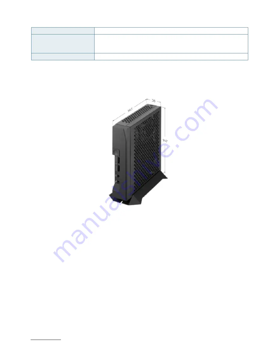
Mechanical Dimensions
Figure 22: Mechanical Dimensions
(unit: mm)


