


COMe-cVR6 – User Guide Rev. 1.5
// 49
7/
Features and Interfaces
7.1.
LPC
The Low Pin Count (LPC) interface signals are connected to the LPC bus bridge located in the CPU or chipset. The LPC
low speed interface can be used for peripheral circuits such as an external Super I/O controller that typically
combines legacy-device support into a single IC. The implementation of this subsystem complies with the COM
Express® specification. The COM Express® Design Guide maintained by PICMG provides implementation information
or refer to the official PICMG documentation for more information.
The LPC bus does not support DMA (Direct Memory Access). When more than one device is used on LPC, a zero delay
clock buffer is required. This leads to limitations for ISA bus and SIO (standard I/O(s) like floppy or LPT interfaces)
implementations.
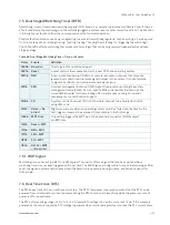
All Kontron COM Express® Computer-On-Modules imply BIOS support for the following external baseboard LPC Super
I/O controller features for the Winbond/Nuvoton 3.3V 83627DHG-P.
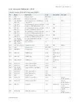
Table 59: Supported BIOS Features
Winbond/Nuvoton 3.3V 83627DHG-P
AMI EFI APTIO V
PS/2
Not supported
COM1/COM2
Supported
LPT
Not supported
HWM
Not supported
Floppy
Not supported
GPIO
Not supported
Features marked as not supported do not exclude OS support (e.g., HWM is accessible via SMB). If any other LPC
Super I/O additional BIOS implementations are necessary then contact Kontron Support.
7.2.
S
erial Peripheral Interface (SPI)
The Serial Peripheral Interface Bus (SPI bus) is a synchronous serial data link standard. Devices communicate in
master/slave mode, where the master device initiates the data frame. Multiple slave devices are allowed with
individual slave select (chip select) lines. SPI is sometimes called a four-wire serial bus, contrasting with three, two
and one-wire serial buses.
The SPI interface can only be used with a SPI flash device to boot from the external BIOS on
the baseboard.
Содержание kontron COMe-cVR6
Страница 1: ...USER GUIDE www kontron com 1 COMe cVR6 Doc User Guide Rev 1 5 Doc ID 1064 6276...
Страница 2: ...COMe cVR6 User Guide Rev 1 5 www kontron com 2 This page has been intentionally left blank...
Страница 22: ...COMe cVR6 User Guide Rev 1 5 www kontron com 22 2 3 2 Block Diagram COMe cVR6 Figure 2 Block Diagram COMe cVR6...
Страница 36: ...COMe cVR6 User Guide Rev 1 5 www kontron com 36 Figure 5 R1000 V1000 PCI Variants...