14
blue
white
green
red
0
12V
A
B
22 26
24
16
73
22
22
22
M+P 26A 2277
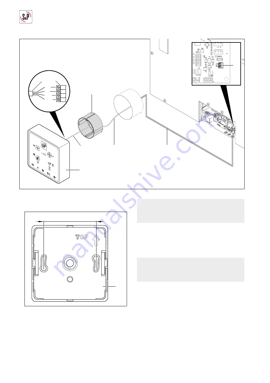
3. Connect cable (22) from the control panel (16) to the
connection (24).
25
60
4. Drill holes for cover of control panel (25) at the inten-
ded installation location.
5. Conduct cable (22) from the wall opening into the
fl ush-mounted box (73).
NOTE
Flush-mounted box (73) is not included in the items
delivered and must be provided on construction.
6. Insert fl ush-mounted box (73) in wall opening.
7. Connect cable (22) to plug (26).
8. Insert control panel (16) into fl ush-mounted box (73)
and screw.
NOTE
No screws are included in the delivered parts. Select
screws with dowels appropriate for the brickwork.
9. Connect ventilation system to power supply.
a pag.26
Содержание NEMBUS 210
Страница 1: ...NEMBUS 210 EN...
Страница 2: ......


