background image

ENGLISH
EDM Axial wall fan
The EDM-300 range extractors have been manufactured to the rigorous standards of production 

and quality as laid down by the international Quality Standards ISO 9001. All the components 

have been checked and all the final products have been tested at the end of the manufacturing 

process.
We recommend you to check the following when receiving this product:
1- That it is the correct size.
2- That it is the correct model.
3- That the details on the rating label are those you require: voltage, frequency…
The installation must be in accordance with the electrical standards in force in your country. 

Installation
IMPORTANT:
 Before installing and wiring the EDM, ensure that the main supply is disconnected.
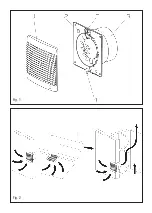
Fig. 1: 

1- Protection grille 

4- Fixing screw


2- Slot 

5- Connection terminals


3- Outlet

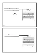
The EDM can be installed on wall or ceiling, and the discharge can be made direct to the outside 

or to a ducting (individual or shunt, fig. 2).
The hole to be made on the wall or the ceiling must have the following diameter: 160 mm 
Loosen the screw (4) fixing the grille (1). Bind the adhesive tape supplied around the outlet (6).
If the installation is made to an individual ducting, use standard ducting: 150 or 160 mm 
Ensure that there are no obstructions to the airflow and that the impeller turns freely.
Fix the extractor to the wall with the 4 plugs and screws supplied in the packaging. The unit must 

be fixed in such a way that it is not stressed, to avoid noise generation or problems in the rotation 

of the impeller. Connect the electrical wiring as explained hereafter and then mount the protection 

grille and fixed it by tightening the screw (4).

Electrical connection
The EDM is an extractor designed for a single phase supply, with voltage and frequency as indi-

cated on the rating plate of the unit. The units are made with double electrical insulation (Class II) 

and therefore they do not need an earth connection.
The electrical installation must include a double pole switch with a contact clearance of at least 

3 mm.
Once the cable has been introduced, through the slot (2), proceed to the appropriate electrical 

wiring depending on the EDM model.

EDM models S and C
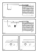
For these models use the following diagrams:
Fig. 3- Switching the extractor through the light switch.
Fig. 4- To switch the fan through an independent switch.

EDM models R and CR
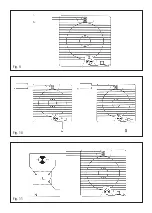
Models fitted with adjustable timer. The timer enables the extractor to continue running during 

the time delay, after the switch has been switched off (Fig. 5). The diagram on Fig. 6 shows how 

to connect a unit fitted with timer using the light switch.
To adjust the timer, turn the rotary switch on the Printed Circuit Board (Fig. 7).

Содержание EDM-300

Страница 1: ...Instrucciones de uso User instructions Notice d utilisation Montageanweisungen Montage Gebruiksaanwijzing Instru es de utiliza o Anv ndar instruktion Instrukcja obslugi Libretto instruzioni EDM 300...

Страница 2: ...Fig 1 Fig 2...

Страница 3: ...Fig 3 Fig 4...

Страница 4: ...Fig 5 Fig 7 Fig 6 Fig 8...

Страница 5: ...Fig 9 Fig 11 Fig 10...

Страница 6: ...jar el aparato a la pared con los 4 tacos y tornillos suministrados en el embalaje Efectuar la conexi n el ctrica tal como se indica a continuaci n volver a montar la rejilla de protecci n y apretar e...

Страница 7: ...la cadena paro marcha fig 10 Funcionamiento autom tico similar al caso 1 y adem s con la posibilidad de poner en marcha el aparato accionando el interruptor con cadena IC cuando el nivel de humedad en...

Страница 8: ...e no obstructions to the airflow and that the impeller turns freely Fix the extractor to the wall with the 4 plugs and screws supplied in the packaging The unit must be fixed in such a way that it is...

Страница 9: ...vel WARNING When the extractor is operating by hygrostat the red pilot lamp on the grille of the EDM is not on Case 2 Auyomatic operation with pull cord override facility Fig 10 Automatic operation as...

Страница 10: ...ndividuel utiliser un conduit de diam tre normalis de 150 ou 160 mm S assurer qu il n existe dans le conduit aucune obstruction au passage de l air Placer l appareil et le fixer l aide des 4 vis et ch...

Страница 11: ...de nouveau inf rieur la valeur indiqu e par le bouton molet ATTENTION Quand l extracteur fonctionne automatiquement par l interm diaire de l hygrostat le t moin lumineux rouge situ sur la face avant...

Страница 12: ...en Dabei sind Sch chte mit folgenden Standardnennweiten zu benutzen 150 160 mm Nach der Montage sollte die Leichtg ngigkeit des Laufrades gepr ft werden Den L fter mit den 4 Schrauben und D beln die...

Страница 13: ...tomatisch abgeschaltet wenn die relative Luftfeuchtigkeit wieder unter den eingestellten Wert f llt ACHTUNG W hrend der Steuerung des L fters ber den Hygrostaten L fter im Automatikbetrieb leuchtet di...

Страница 14: ...t de luchtstroom niet gehinderd wordt en dat de waaier vrij draait Het apparaat aan de wand bevestigen met de 4 pluggen en schroeven bijgeleverd in de verpakking Het apparaat moet zo worden geplaatst...

Страница 15: ...hygrostaat automatisch werkt is het rode controlelampje op het rooster van de EDM uit Grval 2 Automatische werking met mogelijkheid tot handbediening via de aan uit trekschakelaar fig 10 Automatische...

Страница 16: ...tro normalizado 150 ou 160 mm Assegurar se de que n o existe nenhuma obstru o passagem do ar e que a h lice gira livremente Fixar o aparelho parede com os 4 buchas e parafusos fornecidos na embalagem...

Страница 17: ...uando o exaustor funciona utom ticamente gra as ao higrostato a luz piloto encarnada situada na grelha do EDM n o se acende Caso 2 Funcionamento autom tico com possibilidade de se ligar manualmente co...

Страница 18: ...r r skall f ljande diameter p spiror ren anv ndas 150 160 mm Lossa skruven 4 som h ller fronten 1 Linda medf ljande tepj runt utloppet 6 Kontrollera att det inte r n gra stopp i ventilationskanalen sa...

Страница 19: ...rdet Likas st ngs fl kten automatiskt av om luftfuktigheten r l gre i rummet n det inst llda v rdet VARNING N r fl kten r inkopplad med hj lp av hygrostaten t nds ej kontrollampan p fl kten Alternati...

Страница 20: ...go systemu wentylacyinego Fig 2 W przypadku montazu bezposrednio w scianie lub suficie nalezy sykonac otwor o nastepujacej srednicy 160 mm Odkrecajac srube mocujaca 4 nalezy adjac kratke 1 Zalaczona t...

Страница 21: ...y wentylatora uruchamianego przez hydrostat czerwona lampka kontrolna jest wylaczona Spos b 2 Praca automatyczna wylacznik sznurkowy Fig 10 Praca automatyczna podobnie jak w pundcie 1 ale z mozliwosci...

Страница 22: ...ostacolo al passaggio dell aria e che nessun ostacolo impedisca il libero movimento della ventola Fissare l apparecchio alla parete con le 4 viti ed i 4 tasselli cheengono forniti nella scatola d imb...

Страница 23: ...al valore impostato con la manopola Quando il livello d umidit di nuovo inferiore al valore impostato l apparecchio si ferma automaticamente Caso 2 Funzionamento automatico con la possibilit di mette...

Страница 24: ...57 Soler Palau Sistemas de Ventilaci n S L U C Llevant 4 08150 Parets del Vall s Barcelona ESPA A Tel 93 571 93 00 Fax 93 571 93 01 Fax int 34 93 571 93 11 e mail consultas solerpalau com Web www sole...

Отзывы: