background image

1

2

3

4

6

7

6

7

5

8

Fig.1

Fig.2A

Fig.2B

9

3

Fig.1B

Содержание EBB

Страница 1: ...je Instruction leaflet Notice de montage Montageanweisungen Montage en gebruiksaanwijzing Instruções de montagem Istruzioni per l installazione Användar instruktion Instrukcja obslugi Návod Brugervejledning Инструкции по сборке ...

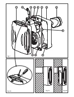
Страница 2: ...1 2 3 4 6 7 6 7 5 8 Fig 1 Fig 2A Fig 2B 9 3 Fig 1B ...

Страница 3: ...Fig 3 Fig 5A Fig 6A N LA LB Fig 4 L N N LA LB L N N LA LB Fig 5B L C N N LA LB L N REB N LA LB Fig 6B EBB S ...

Страница 4: ...Fig 9A Fig 7A L N N L LS L N N L LS N L LS N L LS 15 30 A 2 T min 80 90 70 60 T min HR 20 30 1 10 L N N L LS Fig 7A Fig 7B EBB T EBB HT L N N L LS Fig 8A Fig 8B Fig 9B ...

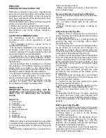
Страница 5: ... be connected to a 100 mm diameter conduit Before assembling the device check that the turbine rotates freely Do not use conduits whose diameter is less than 100 mm If a flexible conduit is used stretch it out fully Do not place elbows right at the extractor discharge Elbows should have as large a radius as possible 1 Make a 105 mm diameter hole in the wall or ceiling making sure that the device f...

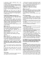
Страница 6: ... Models equipped with an electronic humidistat that can be regulated between 60 and the 90 RH Relative Humidity and with timing that can be set between 1 and 30 minutes When in the timer mode the EBB works at slow speed In order to modify the factory settings the potentiometers situated beside the connections cover fig 9B will have to be operated These potentiometers are fragile and must be handle...

Страница 7: ...soaked in mild detergent Should you observe any anomaly in the operation of the device contact an official authorised service or the seller of the product If the device is handled by persons who are not authorised by S P the guarantee will be cancelled S P reserves the right to make changes without prior notice ATTENTION When the relative humidity level in the area is above the set value automatic...

Отзывы: