FlashDrive Product Manual
FlashDrive Product Manual © 1999 SANDISK CORPORATION
21
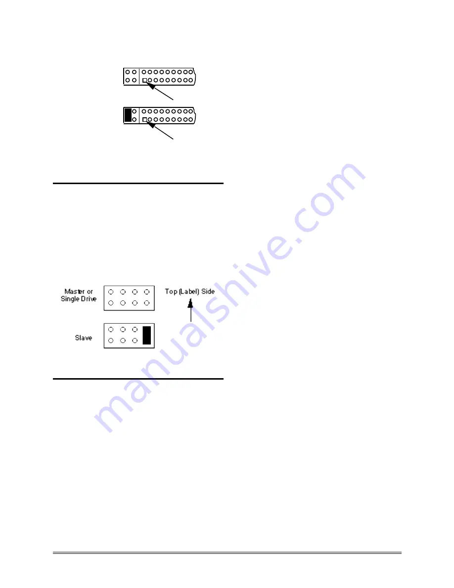
Pin 1
A
B
C
D
Master or
Single Drive
Pin 1
A
B
C
D
Slave
Figure 3-2
2-5-inch FlashDrive Master/Slave
Configuration PIns
3.2.2
Jumper Settings for 3.5-inch FlashDrives
The jumper settings for the 3.5-inch FlashDrive
are shown on the FlashDrive’s label. The
master/slave configuration pins are the eight pins
between the four pin power connector and the 40
pin interface connector. The figure below shows
how the jumpers should be set for either master or
slave configuration on the 3.5-inch FlashDrive.
Figure 3-3
3.5-inch FlashDrive Configuration Pins
3.3
Mounting the FlashDrive
Follow to the steps below to mount the
FlashDrive in your computer system:
1. Connect the FlashDrive to the host
system. If the host system’s cable
connector is not keyed, make sure that pin
1 from the host computer cable is connected
to pin 1 of the FlashDrive. Pin 1 on both
connectors has a square solder pad. If the
FlashDrive is being added to the system
as a slave drive, connect the daisy-
chained connector to the FlashDrive. The
four pin power connector must also be
connected on the 3.5-inch FlashDrive.
2. Mount the FlashDrive into the host
system. The FlashDrive can be mounted in
any orientation from the top, bottom or
side. The 1.8-inch FlashDrives use four
M1.6 screws in the corner mounting holes in
the PC board. The 2.5-inch FlashDrive
uses four M3 screws and the 3.5-inch
FlashDrive uses four 6-32 screws. See
Figures 2-1 through 2-5 and see the
Ordering Information section at the end of
this manual. Ensure that the cables are
not crimped or strained. Make sure that
all mounting screws are hand tightened
securely. For the 3.5-inch FlashDrive,
mounting screws must not extend more than
.25 inch into the frame. For the 2.5-inch
FlashDrive, mounting screws must not
extend more than 3 mm into the frame.
3. Perform the CMOS Setup. If the
computer’s BIOS has an auto-detect
function, use this option, otherwise,
determine if your system has a user
definable “hard drive types” selection in
the CMOS RAM. If your system has this
selection, continue with the CMOS setup.
If your system does not have this
selection, call SanDisk Applications
Engineering at (408) 542-0400.
Refer
to the following table
for
information required to set the user
definable “hard disk type” selection in
your system’s CMOS RAM to the
FlashDrive configuration. The table lists
the number of heads, sectors per track and
cylinders emulated by the FlashDrives.
After
entering
the
appropriate
information, save the new CMOS setup by
rebooting your system.
Содержание SDIB-4
Страница 6: ...FlashDrive Product Manual FlashDrive Product Manual 1999 SANDISK CORPORATION 6...
Страница 16: ...FlashDrive Product Manual FlashDrive Product Manual 1999 SANDISK CORPORATION 16 Figure 2 2 2 5 inch FlashDrive...
Страница 18: ...FlashDrive Product Manual FlashDrive Product Manual 1999 SANDISK CORPORATION 18 Figure 2 4 3 5 inch FlashDrive...
Страница 61: ...FlashDrive Product Manual 1999 SANDISK CORPORATION 61 Ordering Information and Technical Support...
Страница 62: ...62 FlashDrive Product Manual 1999 SANDISK CORPORATION...
Страница 65: ...FlashDrive Product Manual 1999 SANDISK CORPORATION 65 SanDisk Sales Offices...
Страница 66: ...SanDisk Worldwide Sales Offices 66 FlashDrive Product Manual 1999 SANDISK CORPORATION...


