S&C PureWave Скачать руководство пользователя страница 4

4

    S&C Instruction Sheet 653-502

Safety Information

Hazardous Voltages

 DANGER

Potentially lethal voltages are present inside the PureWave UPS System. Dc voltage 
is present even without utility power connected. Hazardous voltages should also be 
expected in all interconnecting components and lines.
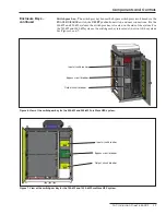
Securing the 

Enclosure

To maintain safety, the user should use padlocks on each enclosure door. The doors and 
the use of the padlocks provide protection against inadvertent contact with high-voltage 
circuits.

Safety Equipment, 

Precautions, and 

Practices

S&C PureWave UPS System and battery instruction sheets must be available to all 
operators and other employees. If doors to the electrical controllers or panels to the 
system enclosure must be opened, refer to the instruction sheet for procedures for 
guarding against electric shock. Lockout and tagout procedures should be developed 
and implemented in accordance with 29 CFR 1910.147.

 WARNING

Insulated hand tools are required when working on or around any energized equipment. 
Use only properly rated tools for the energy present. Tool inventories should be kept 
to ensure all tools that enter the system enclosure are removed before energizing the 
system.

Emergency 

Procedures and 

Equipment

The owner should develop policies and procedures for handling emergency situations. 
It is the responsibility of the owner to develop site-specific emergency action plans for 
response to such situations.

Additional Safety 

Instructions

Consult the supplier of the batteries for additional safety instructions and procedures.
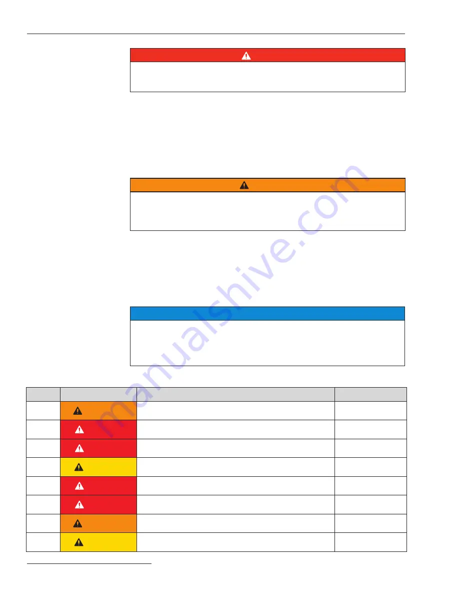
Location of Safety 

Labels

NOTICE

For safety labels, contact S&C Electric Company for the following:
•  Exact location of the standard safety labels
•  Project-specific safety labels 
•  Replacement of labels (reference the label part numbers as shown below)

Reorder Information for Safety Information

Location Safety Alert Message

Description

Part Number

A

 WARNING

Keep out. Risk of electric shock…

PE-70314

B


DANGER

Hazardous voltage…

PE-70315

C


DANGER

Keep out. Risk of electric shock…

PE-70323

D

 CAUTION

Do not remove power conversion…

PE-70321

E


DANGER

Hazardous voltage inside…

PE-70319

F


DANGER

Risk of electric shock…

PE-70316

G

 WARNING

To reduce risk of fire...

PE-70324

H

 CAUTION

Always follow the instructions...

PE-70325

Содержание PureWave

Страница 1: ...ructions 4 Location of Safety Labels 4 Safety Precautions 13 Shipping and Handling 13 Inspection 13 Components and Controls Enclosure Configurations 14 Enclosure Bays 16 Doors 19 LCD Screen 20 Air Con...

Страница 2: ...e a location where you can easily retrieve and refer to it Proper Application WARNING The equipment in this publication must be selected for a specific application The application must be within the r...

Страница 3: ...ns including recommended precautions are not followed NOTICE NOTICE identifies important procedures or requirements that can result in product or property damage if instructions are not followed Follo...

Страница 4: ...roperly rated tools for the energy present Tool inventories should be kept to ensure all tools that enter the system enclosure are removed before energizing the system Emergency Procedures and Equipme...

Страница 5: ...S C Instruction Sheet 653 502 5 Location of Safety Labels continued For 750 kW and 1000 kW PureWave UPS Systems 1000 kW system pictured Safety Information A A A A B B D F A B D F...

Страница 6: ...6 S C Instruction Sheet 653 502 Safety Information Location of Safety Labels continued For 750 kW and 1000 kW PureWave UPS Systems 1000 kW system pictured A B D F C A A B D F B B C C...

Страница 7: ...502 7 Safety Information Location of Safety Labels continued For 750 kW and 1000 kW PureWave UPS Systems 1000 kW system pictured A B D C G E Inside wall of the circuit breaker section of the switchge...

Страница 8: ...n Location of Safety Labels continued For 750 kW and 1000 kW PureWave UPS Systems View of the back side of the circuit breaker section door of the switchgear bay View of the back side of the swing out...

Страница 9: ...S C Instruction Sheet 653 502 9 Safety Information Location of Safety Labels continued For 250 kW and 500 kW PureWave UPS Systems 500 kW system pictured A A A A A...

Страница 10: ...10 S C Instruction Sheet 653 502 Safety Information Location of Safety Labels continued For 250 kW and 500 kW PureWave UPS Systems 500 kW system pictured B E C B C B B E E...

Страница 11: ...nstruction Sheet 653 502 11 Safety Information Location of Safety Labels continued For 250 kW and 500 kW PureWave UPS Systems E E E Views of the control bay with the door open showing the dead front p...

Страница 12: ...12 S C Instruction Sheet 653 502 Safety Information Location of Safety Labels continued For 250 kW and 500 kW PureWave UPS Systems E H G E E E E H G View of the switchgear bay with door open G...

Страница 13: ...directed by S C Electric Company 6 ENERGIZED COMPONENTS Always consider all parts live until de energized tested and grounded 7 GROUNDING For grounding purposes the proceeding must be followed The Pu...

Страница 14: ...hen the unit is properly grounded Never under any circumstances open the enclosure doors while it is online or has not been fully discharged and grounded Failure to do this can result in equipment dam...

Страница 15: ...Battery bay Control bay Battery bay Battery bay Switchgear bay LCD Figure 3 Front view of the 750 kW PureWave UPS System Battery bay Control bay Battery bay Battery bay Battery bay Air conditioner Ai...

Страница 16: ...and a power conver sion module PCM The PCM is located in its own compartment in the battery bay and is comprised of one inverter module consisting of power conversion electronics and con trols The PCM...

Страница 17: ...the switchgear bay is located on the side of the system For the 750 kW and 1000 kW systems the switchgear bay is located at the front of the system See Figures 6 and 7 Input circuit breaker Output ci...

Страница 18: ...the monitoring computer control system power electronic switch PES and ac filter capacitor In addition an EMERGENCY DISABLE mushroom switch and a RESET pushbutton are located behind the door See Figu...

Страница 19: ...ee bolts so they detach from the enclosure the bolt will not completely detach from the door The door will now open Once the door is opened approximately 90 degrees or 135 degrees engage the lock bar...

Страница 20: ...ccRrrr Indicates the configuration revision of the firmware running in the PureWave UPS System Test Run Request Indicates the PureWave UPS System has received a manual Run request Table 1 General Mess...

Страница 21: ...Enable position the system is enabled With the switch in the Disable position the system is disabled When the system is dis abled the system will go to the Bypass Isolate state connecting the utility...

Страница 22: ...struction Sheet 653 502 Operating Controls continued Components and Controls Figure 12 Location of the operating controls for the 750 kW and 1000 kW PureWave UPS Systems ENABLE DISABLE switch RESET pu...

Страница 23: ...he location of these controls ENABLE DISABLE This mushroom pushbutton performs the same functionality as the toggle switch in the switchgear bay This button serves as an Emergency Stop for service per...

Страница 24: ...tus of the PureWave UPS System The computer is located on the back of the swing out panel located in the control bay Information from the computer can be accessed via an Ether net connection See Figur...

Страница 25: ...ve UPS System is not protecting the load from power disturbances The following optional contacts are available The contacts operate as follows if provided Low Battery The Low Battery contact will annu...

Страница 26: ...a voltage matching isolation transformer while the PES is com manded off open to isolate the customer s critical loads from the faulted utility Output power matches the customer load for one minute a...

Страница 27: ...nsition States Listed in Table 3 are the transition states of the PureWave UPS System These temporary states occur while the PureWave UPS control logic is transitioning from one primary state to anoth...

Страница 28: ...ver 40 C 104 F Troubleshooting Tip The air conditioners may not be working or they may not be able to keep up with the temperature rise Check the output block that turns on the contactors and the circ...

Страница 29: ...ency Troubleshooting Tip The system will respond based on the under frequency settings The frequency threshold can be changed if desired Utility Under Voltage Indicates the system is sensing a utility...

Страница 30: ...iption Fire Hot Temp Zone Indicates temperature is over 65 C 149 F at the designated bay Troubleshooting Tip There is a fire in the designated zone Contain the fire and then contact S C Electric Compa...

Страница 31: ...ureWave UPS system s input and output circuit breakers are open and the bypass circuit breaker is closed If the bypass circuit breaker did not close and the input and output circuit breakers did not o...

Страница 32: ...trically con nected to the transfer switch via a dry contact Actuating the contact transfer signal commands the transfer switch to start the generator and transfer to the generator after the generator...

Страница 33: ...t S C Electric Company to obtain the username and password for access to the monitoring program if you forget your username and or password Monitoring Software One Line Screen After the user name and...

Страница 34: ...is open If these icons are red the circuit breaker or switch is closed Load If this icon is red the load is being supplied with power If this icon is green the load is not being supplied with power F...

Страница 35: ...on the One Line screen Monitoring Software continued Displayed Parameters Figure 18 shows the areas of the One Line screen where the user can find measured parameters of the PureWave UPS System Power...

Страница 36: ...itoring Software continued Status Screen The Status screen shows all the alarms for the PureWave UPS System and displays the active alarms using color indicators In addition the screen shows the curre...

Страница 37: ...on the given site conditions and if required the frequency of the recommended maintenance may increase to ensure the reliability of their PureWave UPS System S C Electric Company has extended service...

Страница 38: ...and flat head screwdriver DAP concrete sealant PureWave UPS System enclosure touch up paint Verified By _________________________ Date ___________ Arrival Jobsite name ________________________________...

Страница 39: ...going into the PureWave UPS System Inspect the air inlet filter inside of the switchgear bay door for debris and obstructions that can cause air flow restrictions The filter can be replaced by unbolti...

Страница 40: ...debris and obstructions that can cause air flow restrictions See Figure 22 The filter can be replaced by unbolting the top of the air inlet vent hood with a wrench and screwdriver When the hood is op...

Страница 41: ...sekeeping to ensure there no garbage or debris is in or around the enclosure Bring the PureWave UPS System back online Record the system state _______________________________________________________ C...

Страница 42: ...the doors to the PureWave UPS System enclosure s Confirm with the site facilitator that the PureWave UPS System is de energized Verified By _________________________ Date ___________ Required Tools Sh...

Страница 43: ...PureWave UPS enclosure Visually inspect the outside of the enclosure for signs of deterioration or rust Rust found YES or NO circle one If yes clean the rust and paint using the correct paint color fo...

Страница 44: ...ric Company Follow these steps for each battery bay Inspect the top and bottom hydrogen vents located along the inside wall of the bay Clean any debris or obstructions that can restrict air flow See F...

Страница 45: ...an restrict air flow going out of the PureWave UPS System See Figure 25 for the location of the air outlet vent hood Inspect the control panel and the monitoring computer at the back of the swing out...

Страница 46: ...the air inlet filter inside of the switchgear bay door for debris and obstructions that can cause air flow restrictions The filter can be replaced by unbolting the mounts with a inch wrench or socket...

Страница 47: ...air inlet The contact of conductive materials or tools with energized parts inside the equipment can result in serious equipment damage personal injury or even death Inspect the air inlet filter for...

Страница 48: ...ments in Table 8 below Hold your hand under each of the air conditioners to verify cool air is still being produced Record the ambient temperature when air conditioner testing is being performed Repla...

Страница 49: ...al housekeeping to ensure no garbage or debris is in or around the enclosure Bring the PureWave UPS System back online Record the system state _______________________ Close and lock all the enclosure...

Отзывы: