background image

Содержание AS-1A

Страница 1: ...ECTRIC CANADA LTD Toronto I Section Page Number INSPECTION SCHEDL LE AND PROCEDURES 18 CHECKING SWITCH OPERATOR AND ALDlJTI RFPTER SWITCH POSITIONS 20 APPENDIX Amended Travel Limit Adjustment Procedur...

Страница 2: ...operatmg mPehamsm rotation lyp1cal nmning spPPd of sw1teh operator output haft 26 revolut10ns per mmute 769 500 INSTRUCTION SHEET Page 2 of 23 April 22 1996 in internal decoupling mechanism mechanical...

Страница 3: ...Compatibility Permits use of switch operator with S C Micro AT Source Transfer Control in Weather U1 proof EnclosureCD Duplex Receptacle and Convenience Light Lampholder with Switch V Extra Auxiliary...

Страница 4: ...OTICE identifies important procedures or require ments that if not followed can result in product or property damage if instructions are not followed 769 500 INSTRUCTION SHEET Page 4 of 23 April 22 19...

Страница 5: ...tion Install and tighten the self locking nuts Do not use lockwashers with the flexible coupling attachment bolts Remove the clamp bolts and set aside the detachable half of the flexible coupling Atta...

Страница 6: ...or contactor closing I lowest section of vertical operating pipe will of course be cradled in the open flexible coupling attached to the output shaft of the switch operator While holding the pipe sect...

Страница 7: ...ove the blocking from the motor contactors I Connect the external control circuit wiring including space heater source leads to the terminal blocks of the switch operator in accordance with the wiring...

Страница 8: ...h the user and S C Electric Company IMANUAL OPERATION Before proceeding further familiarize yourself with the operation of the manual operating handle and the selector handle as described on the switc...

Страница 9: ...ng the operating handle backward approximately 90 degrees until it latches in the storage position Note that the manual operating handle may be disen gaged from the switch operator mechanism at any po...

Страница 10: ...tion for coupling turn the manual operating handle slowly until the position indexing drums are numerically aligned Then swing the selector handle upright and rotate it counterclockwise to the coupled...

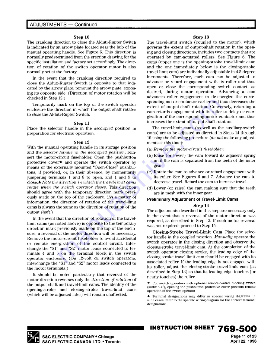
Страница 11: ...go S C ELECTRIC CANADA LTD Toronto I Step 13 The travel limit switch coupled to the motor which governs the extent of output shaft rotation in the open ing and closing directions includes two contacts...

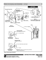
Страница 12: ...limit cam in lowered position Adjacent spring Closing stroke travel limit cam with switch operator in fully open position lower and turn cam clockwise to increase travel of switch operator Use when di...

Страница 13: ...nd replace the motor circuit fuseholder Figure 7 Adjustment of cams on auxiliary switch S C ELECTRIC COMPANY Chicago S C ELECTRIC CANADA LTD Toronto I Operate the switch operator electrically to open...

Страница 14: ...ose the switch Remove the motor circuit fuseholder 769 500 INSTRUCTION SHEET Page 14 of 23 April 22 1996 I To increase travel in the opening direction retard the opening stroke travel limit cam one 4...

Страница 15: ...g numbers with either the suffix W or Z are equipped with an extra auxiliary switch which is pem1anently coupled to the Alduti Rupter S C ELECTRIC COMPANY Chicago S C ELECTRIC CANADA LTD Toronto I Swi...

Страница 16: ...fix W or Z Figure 8 Standard contact configurations 769 500 INSTRUCTION SHEET Page 16 of 23 April 22 1996 Travel limit switch auxiliary switch i a and extra auxiliary Open front view of switch operato...

Страница 17: ...losed b2 contacts open Alduti Rupter Switch in fully closed position S C ELECTRIC COMPANY Chicago S C ELECTRIC CANADA LTD Toronto I Travel limit switch a1 contacts open Auxiliary switch 8 PST b1 conta...

Страница 18: ...is set screw approximately one half turn using a 1 s Allen wrench before removing the motor 769 500 INSTRUCTION SHEET Page 18 of 23 April 22 1996 i e Using a 211 Allen wrench loosen the pad assem bly...

Страница 19: ...ee play Brake lever Operating linkage connected to brake lever Point of initial manual brake release 1 a 1 4 travel DETAILD 20 socket head set screw 1 a Allen wrench required DETAILC Location of motor...

Страница 20: ...SHEET Page 20 of 23 April 22 1996 Then tag and padlock the switch operator in accor dance with standard system operating procedures In all cases make certain that the switch operator is padlocked befo...

Страница 21: ...uit fuseholder and operate the switch operator to the open position g If the direction of output shaft rotation to open the Alduti Rupter Switch is opposite to that displayed in the cutaway section on...

Страница 22: ...n thE outer ring is in line with the number 5 on the indicator plate Raise the disc make sure it is engaged and release the handwheel 769 500 INSTRUCTION SHEET Page 22 of 23 April 22 1996 i StepD To p...

Страница 23: ...Switch was not attained replace the motor circuit fuseholder and operate the switch operator electrically to open the Alduti Rupter Switch Remove the motor circuit fuse S C ELECTRIC COMPANY Chicago S...

Отзывы: