GS-818 GPS/GSM/GPRS Vehicle Tracker User Manual
52 Copyright © 2011 San Jose Technology, Inc. All Rights Reserved.
I/O Input Detection Activation
GS-818 I/O provides totally 8 input pins and 2 output pins for versatile vehicle input/output applications as the following
table:
I/O Pin
Type
QTY
Specification
Main Application
ACC
1
3-40V, high trigger
Ignition ACC status detection (Please refer to ACC Status
Detection)
Analog
2
0-40V
Fuel sensor/ Temperature &Humidity Transmitter
2
3-40V
Door Open/ Wipers… detection
Input
Digital
3
0-0.6V
Reed/ Relay
Output
Analog
2
8-35V/300mA
Lamp/ Speaker
Table: I/O Type and Application Description
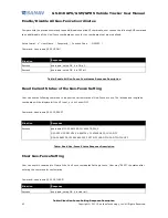
Use this command to switch on or off the I/O digital input detection. There are 5 digital input detection pins. When
detecting the devices in vehicle like door open, wipers on, music on or lamp on…etc status, the GPRMC data will be
reported with “alarmx” Tracker Status message. The x means the number of I/O pin.
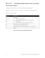
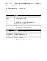
Command format: #
「
username
」
,
「
Password
」
,
「
io number
」
,
「
0 or 1
」
*
Command: #username,0000,io1,0*
Table: I/O Digital Input Setup Format Description
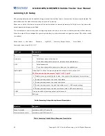
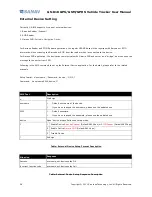
Table: I/O Digital Input Setup Response Description
SMS Text
Description
#
Start sign.
username
*Default user name of the device.
*If you have changed the username, please use the updated one.
0000
*Default password.
*If you have changed the password, please use the updated one.
io1
Mode “io1” defines io1 status setup mode. io1 to io5 setup are available
0/1
0 Switch off the digital i/o input
1 Switch on the digital i/o input
*
End sign.
Situation
Response
Success(Switch on I/O)
username, setup OK. Device I/O (1-5) detection is switched on
Success(Switch off I/O)
username, setup OK. Device I/O (1-5) detection is switched off


