SAMUEL JACKSON HO-1-114 Скачать руководство пользователя страница 25


PAGE 

21

 of 

32

  HO-1-1143 OIL-FIRED HEATER 

© SAMUEL JACKSON, INCORPORATED, 2009 ALL RIGHTS RESERVED 

Troubleshooting Guide, continued


If both motors are running but the burner will not ignite: 
 

1.


Check that the target temperature (SP) displayed on the digital temperature 
controller is above the actual measured temperature PV (process variable).  The 
controller will only “call for heat” and start the burner when the process variable 
is lower than the target. 


2.


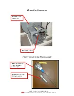
Check that at least 100 PSI (6.9 bar) pressure is registering on the fuel nozzle 
pressure gage. If no pressure is registering or the pressure is oscillating, the fuel 
supply system is not primed. See “Priming the Fuel Pump” section in manual. 


3.


Press the red RESET on the heater’s Primary Burner Control. If the burner does 
not light, check the following: 


Fuel in supply tank 


Fuel filters are clean 


Igniter electrodes are adjusted correctly 


Fuel nozzle and filter are in good shape 


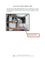
Burner air shutters and nozzle line adjustment plate are adjusted correctly  


After checking all the above and lockout continues to occur without an 
obvious reason, consult the factory.  


The burner is on, but the actual temperature remains below the target temperature: 
 

1.


The fuel nozzle pressure probably needs adjusting. The normal range for the 
nozzle pressure is 100 to 200 PSI (6.9 to 13.8 bar). See “Adjusting Fuel Pressure 
for Heat Output from Burner” for more information. 


The burner is on but there is excessive smoke in the outlet air: 
 

1.


Check that the nozzle pressure is between 100 to 200 PSI (6.9 to 13.8 bar). 


2.


Check that the burner air shutters and nozzle tube assembly adjustment plate are 
adjusted according to this manual. 


3.


Replace the oil nozzle with Part No. 23263 nozzle stamped 3.50. 


4.


Check the static air pressure at the outlet of the heater. A positive pressure here is 
ok but a negative static pressure below -0.8 inches water column may not be. 
Consult the factory. 
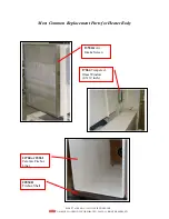
 

5.


Check that the 22760 or 23261


Ceramic Firebox Liner is intact. 

 
6.


Check that only diesel, No. 2 fuel oil or kerosene is being used for fuel. Consult 
the factory for special adjustments if you plan to operate the burner on kerosene. 

Содержание HO-1-114

Страница 1: ...HO 1 1143 700 000 Btu Hr Oil Fired Heater...

Страница 2: ...PAGE 2 of 32 HO 1 1143 OIL FIRED HEATER SAMUEL JACKSON INCORPORATED 2009 ALL RIGHTS RESERVED...

Страница 3: ...Control 10 Adjusting the Heater Output Temperature 11 Adjusting Fuel Pressure for Heat Output from Burner 12 Adjustment of Air Shutter Band on Burner 13 Nozzle Tube Assembly Adjustment Plate 14 Clean...

Страница 4: ...mponents In the future when you require service technical support or parts please contact us by phone fax or the internet Our engineers and service people are available to assist you in obtaining the...

Страница 5: ...and we will gladly send you the latest product information DANGER Please read and understand all the warnings below before operating or maintaining a Samuel Jackson product If you do not understand ca...

Страница 6: ...uel Jackson approved parts Do not work on any Samuel Jackson product without first following OSHA Lockout Tagout procedures Confirmation by a licensed electrician that there is no electricity present...

Страница 7: ...el Oil or Kerosene Heater Capacity 250 000 BTU hr to 0 7 million BTU hr Control Temperature set point with on off firing mode Air Volume Up to 4 000 cubic feet minute depending on static pressure at h...

Страница 8: ...hat all necessary connections for electrical and fuel are made Standard electrical power supply for the heater is 3 phase 230 VAC 50 60 HZ and single phase 230 VAC 50 60 HZ Refer to drawing CA15562 in...

Страница 9: ...ed See the Cleaning the Fuel Filter section in the manual If the supply tank is overhead make sure that the head pressure does not exceed 3 PSI or permanent damage can occur to the fuel oil pump A inc...

Страница 10: ...the total resistance to air flow for the duct system TIPS It is better to change the speed of the fan to get close to the desired air volume than severely gating down the air flow from an over sped f...

Страница 11: ...r fan should start Check if the motor on the Beckett burner is on If the Beckett burner motor is off slowly adjust the air flow switch adjusting screw counter clockwise until the motor comes on then c...

Страница 12: ...bustion air and fuel pump and digital temperature controller will power on After a few seconds of self checks by the primary burner control the burner should light provided that the air flow switch is...

Страница 13: ...air bleed valve Adjust oil nozzle pressure between 100 to 200 PSI 6 9 to 13 8 bar The fuel delivery piping has been set up as a two pipe system A 1 16 inch bypass plug was installed inside the return...

Страница 14: ...l The Primary Burner Control provides automatic burner sequencing and flame supervision If flame is not established within the 15 second trial for ignition period the control shuts down on safety lock...

Страница 15: ...rease or decrease the target SP temperature The thermocouple will quickly respond to heater output changes if the thermocouple is placed in the air pipe just after the heater s outlet In this case adj...

Страница 16: ...rature conditions may require fine tuning the fuel pressure after startup Too high of fuel pressure will increase cycling Too little fuel flow will make achieving the target temperature take longer or...

Страница 17: ...e amount of air flow area available to the burner for good combustion These have been pre set at the factory for the anticipated firing rates using the standard Part No 23263 oil nozzle stamped 3 50 a...

Страница 18: ...Plate The nozzle tube assembly adjustment plate has been set at the factory to 5 for the anticipated firing rates using the standard Part No 23263 oil nozzle stamped 3 50 and will seldom need to be a...

Страница 19: ...at the burner can operate at the best efficiency and prevent damage to the fuel pump The fuel filter is located below the control panel on the fuel supply line Close the fuel valve Be prepared for fue...

Страница 20: ...ent combustion The oil nozzle should be replaced each year Below are steps for removing the oil nozzle and adjusting the igniter electrodes Be certain that power has been turned off and lockout tagout...

Страница 21: ...TED 2009 ALL RIGHTS RESERVED Replacing the Oil Nozzle and Adjusting the Igniter Electrodes continued Carefully slide the oil nozzle tube with igniter electrodes out of burner housing Loosen screw on i...

Страница 22: ...ACKSON INCORPORATED 2009 ALL RIGHTS RESERVED Replacing the Oil Nozzle and Adjusting the Igniter Electrodes continued Remove nozzle Use a backup wrench to hold the nozzle tube The nozzle screen can be...

Страница 23: ...IGHTS RESERVED Replacing the Oil Nozzle and Adjusting the Igniter Electrodes continued After replacing the nozzle use the diagram below to adjust the igniter electrodes Dimensions shown are in inches...

Страница 24: ...oad relay is not tripped If the heater fan is running but the burner motor is not running 1 Check and adjust the air flow switch See Adjusting the Air Flow Switch section 2 Check 230 VAC single phase...

Страница 25: ...tment plate are adjusted correctly After checking all the above and lockout continues to occur without an obvious reason consult the factory The burner is on but the actual temperature remains below t...

Страница 26: ...PAGE 22 of 32 HO 1 1143 OIL FIRED HEATER SAMUEL JACKSON INCORPORATED 2009 ALL RIGHTS RESERVED...

Страница 27: ...PAGE 23 of 32 HO 1 1143 OIL FIRED HEATER SAMUEL JACKSON INCORPORATED 2009 ALL RIGHTS RESERVED...

Страница 28: ...TER SAMUEL JACKSON INCORPORATED 2009 ALL RIGHTS RESERVED Burner Components Contact factory for CF500 Burner parts not individually labeled below 23263 Fuel Nozzle stamped with 3 50 is standard 23262 C...

Страница 29: ...ED 2009 ALL RIGHTS RESERVED Heater Control Cabinet Components 17250 Air Flow Switch Assembly 22217 Contactor 14736B Overload Relay for Burner Motor 22217 Contactor 21538 Overload Relay for Heater Fan...

Страница 30: ...6 of 32 HO 1 1143 OIL FIRED HEATER SAMUEL JACKSON INCORPORATED 2009 ALL RIGHTS RESERVED Heater Control Cabinet Components continued 23189 UDC 2500 Universal Digital Controller digital temperature cont...

Страница 31: ...ED HEATER SAMUEL JACKSON INCORPORATED 2009 ALL RIGHTS RESERVED Most Common Replacement Parts for Heater Body 22760 or 23261 Ceramic Firebox Liner 13530A Air Intake Screen 17064 Tempered Glass Window 4...

Страница 32: ...ER SAMUEL JACKSON INCORPORATED 2009 ALL RIGHTS RESERVED Heater Fan Components Temperature Sensing Thermocouple 23149 Fan with 3 HP motor 23230 B42 V Belt 16900C Exposed Tip Type J Shrouded Thermocoupl...

Страница 33: ...PAGE 29 of 32 HO 1 1143 OIL FIRED HEATER SAMUEL JACKSON INCORPORATED 2009 ALL RIGHTS RESERVED...

Страница 34: ...PAGE 30 of 32 HO 1 1143 OIL FIRED HEATER SAMUEL JACKSON INCORPORATED 2009 ALL RIGHTS RESERVED...

Страница 35: ...et the particular requirements Implementation of alternative safety devices may incur additional charges No warranty of compliance with a particular standard is made in the absence of specific referen...

Страница 36: ...PAGE 32 of 32 HO 1 1143 OIL FIRED HEATER SAMUEL JACKSON INCORPORATED 2009 ALL RIGHTS RESERVED This page intentionally blank...

Отзывы: