6-3
6. PCB Diagram
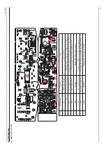
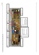
6-2. Detailed Connector and Relay T
erminal Block Manual (Main PCB)
CN8
AG+: Connected to Silver Nano
ሪ
CN3
Connected to the
AC
power
ሪ
CN5
Connected to the Sensing Block
1.
Connected to the water level
sensor
.
2.
Connected to the water level
sensor
.
3. NC
4. Connected to the Ground.
5. Connected to the Door Checker
.
6. NC
ሪ
CN4
FLASH: MICOM WRITING
ሪ
CN6
Connected to the right
terminal of the motor
.
ሪ
CN7
Connected to the left terminal of
the motor
.
ሪ
CN2
Connected for the
Ag operating
control
ሪ
&1
Connected to the Drive Block
1. NC
2. NC
3. Connected to the Drain.
&RQQHFWRW9
DOYH
&RQQHFWHGWRWKH&ROG9
DOYH
6. Connected to the Rinse.
ሪ
CN1
Connected to the
AC
power
.
ሪ
Содержание WA10VP
Страница 25: ...3 12 3 Disassembly and Reassembly Memo ...
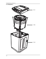
Страница 27: ...5 2 SORGHG 9LHZV DQG 3DUWV LVW 5 1 MAIN BEST P0001 U0084 F0062 ...
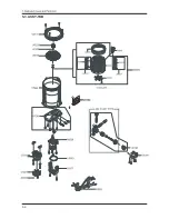
Страница 31: ...5 6 5 3 ASSY TUB 262 9 4 ...
Страница 38: ...6 4 6 PCB Diagram Memo ...
Страница 40: ...7 2 UG Gk Mome ...
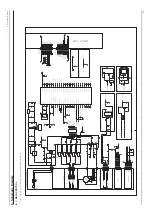
Страница 41: ...8 1 _UGz Gk 1 Vfkhpdwlf Gldjudp 041 PDLQ FRQWURO G Gk G G G G G Gz G U ...
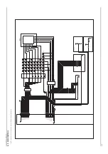
Страница 42: ...8 2 _UGz Gk 051 VXE FRQWURO G Gk G G G G G Gz G U ...


